This is the Revision A version of the Emulate RoboBrick. The status of this project is work in progress.
This document is also available as a PDF document.
The Emulate board uses a 28-pin PIC16F876 with flash memory to emulate a PIC12C519, a PIC12C672, or a PIC16C505. When developing software for the PIC16F876, the flash memory is easier to erase than the other parts which require a UV light to erase them.
To improve readability, the part numbers are truncated down to the last three digits (i.e. PIC12C519 => '519, PIC16C505 => '505, etc.)
The relevant differences between '519, '672, '505, and '876 are summarized in the table:
Since the RoboBricks are all being programmed in µCL, the differences between these microcontrollers can largely be ignored.
'519 '672 '505 '876 Package 8-pin DIP 8-pin DIP 14-pin DIP 28-pin (narrow) DIP Program Memory 1K × 12 2K × 14 1K × 12 8K × 14 Data Memory 41 128 72 368 First Free Memory 7 7 0xC 0x20 A/D None 4 Ch./8-bit None 5 Ch./10-bit I/O Pins 5 I/O, 1 Input Only 5 I/O, 1 Input Only 11 I/O, 1 Input Only 22 I/O
The pin outs for the '519, '672, and '505 are summarized in the table below:
Of particular importance to note is that 8-pin packages of the '519 and '672 map nicely onto the 14-pin package of the '505. The power, ground, and GP0-5 lines of the '519 and '672 line up with power, ground and RB0-5 lines of the '505. This means that a single 14-pin connector (N1) can be used to connect the Emulate RoboBrick to other RoboBricks that use the '519, '672, or '505. For the '519 and '672, a single 8 conductor ribbon cable is used, and for the '505, a 14 conductor ribbon cable is used.
Pin (DIP8) '519 '672 Pin (DIP14) '505 1 VDD VDD 1 VDD 2 GP5/OSC1/CLKIN GP5/OSC1/CLKIN 2 RB5/OSC1/CLKIN 3 GP4/OSC2 GP4/OSC2/AN3/CLKOUT 3 RB4/OSC2/CLKOUT 4 GP3/MCLR*/VPP GP3/MCLR*/VPP 4 RB3/MCLR*/VPP 5 RC5/T0CKI 6 RC4 7 RC3 8 RC2 9 RC1 10 RC0 5 GP2/T0CKI GP2/T0CKI/AN2/INT 11 RB2 6 GP1 GP1/AN1/VREF 12 RB1 7 GP0 GP0/AN0 13 RB0 8 VSS VSS 14 VSS
In µCL, the first I/O port is always labeled A, the second B, the third C, etc. The binding between µCL ports and their corresponding microcontroller ports are summerized below:
{Actually, I think this table is still a little screwed up and I do not feel like figuring it out right now.}
µCL Port '672 '519 '672 '505 A RA0-5 GP0-5 GP0-5 RB0-5 B RB0-7 RC0-5 C RC0-7
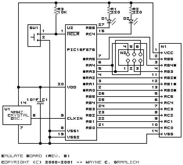
The '672 has for 4 analog inputs on pins GP0-GP2 and GP4. The '876 has 5 analog inputs on pins RA0-3 and RA5. Furthermore, the '876 has 10-bit A/D and the '672 has 8-bit A/D. The jumper block J1 can be used to swap RA3 and RA4 so that the analog input on GP4 of the '672 is routed to the analog input on RA3 of the '876. This swap must be dealt with in the µCL emulation software. The 8 vs. 10 bit A/D conversion resolution must be dealt with in software as well.
The hardware consists of a circuit schematic and a printed circuit board.
The schematic for the EMULATE RoboBrick is shown below:
The parts list kept in a separate file -- emulate.ptl.
The printed circuit files are listed below:
The following issues came up with the revision B version of the Emulate RoboBrick: