This is the construction instructions for the
BS2Hub8 (rev. C) RoboBrick. The status of this project is
work in progress.
BS2Hub8 RoboBrick (Revision C) Construction
The instruction steps for building the BS2Hub8
(Rev. C) RoboBrick are listed below:
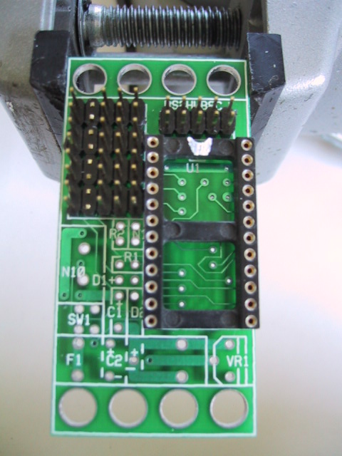
-
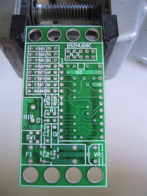
Orient the board vertically with N1 in the
upper left corner.
[step1.jpg]
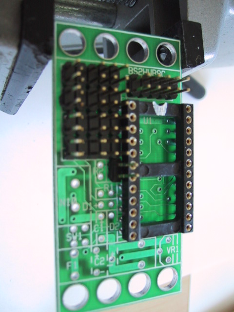
-
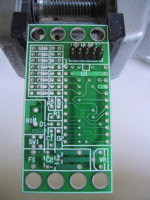
Take a 2×5 male header and install it
at N9. When installing, start by soldering
only one pin. Then turn the board upside
down and verify that the connector is properly
seated. If not, re-heat the pin you initially
soldered and re-seat the connector. When you
are satisfied that the connector is properly
seated, turn the board back over again and
solder the remaining 9 pins.
[step2.jpg]
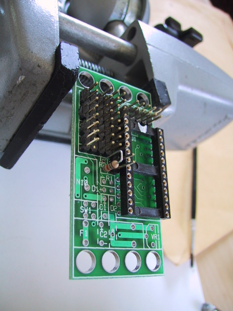
-
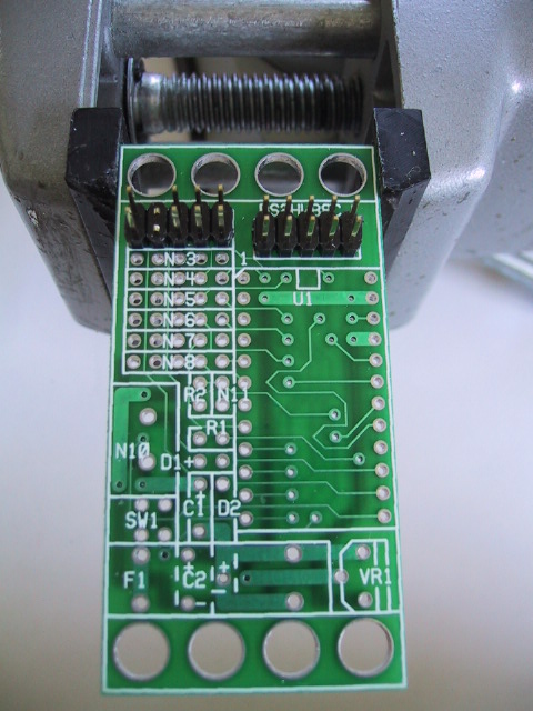
Take another 2×5 male header and orient
it horizontally. Using some diagonal cutters,
snip off 2 pins corresponding to pins 3 and 4
in the diagram below:
Pins 3 and 4 are in the positions marked `X'.
Using the same procedure as in the previous
instruction, install the 2×5 header at
position N1 and N2. The snipped of pins must
be on the left side. Again, solder one pin
first, verify seating, and solder the remaining
nine pins.
[step3.jpg]
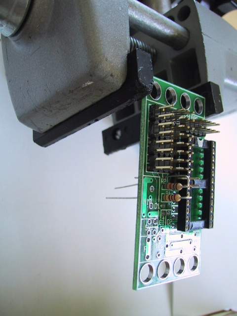
-
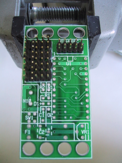
Using the same procedure as the preceding
instruction, install 3 more 2×5 headers
at positions N3&N4, N5&N6, and N7&N8
respectively. Again, be sure to snip off the
two pins prior to soldering one pin, verify
seating, and solder the remaining pins.
[step4.jpg]
-
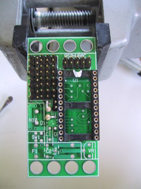
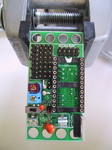
Take the 24-pin IC socket and orient it so
that the notch is pointing up. Frequently,
the IC sockets are not very well marked as
to which pin is pin 1. If the socket gets
installed upside down, no real harm is done,
since the socket is symmetrical. As with
the male headers, solder 1 pin first,
verify seating, and solder the remaining
23 pins. In the picture, the notch is
highlighted with some white ink.
[step5.jpg]
-
Take a 1×2 male header and install it
at position N11. There may be a little
interference between N11 and the IC socket.
If so, sand, file, or scrap off a little
on the edge of N11 until it fits in without
tipping over any. Again, solder 1 pin,
verify seating, and solder the remaining pin.
[step6.jpg]
-
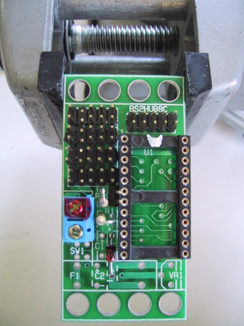
Find the 10K Ohm resistor. It has a color
code of Brown-Black-Orange. Frequently,
orange is followed by a Gold or Silver
band. This is resistor R2 and it is going
to be installed vertically. With the
Brown band on top, bend the lead 180 degrees
until it is pointing down. (Resistors
are symmetrical, so no harm is done if
you have the gold band on top.) Insert
the lead coming out the bottom (i.e. near
the gold band) into the bottom hole of R2;
the remaining lead goes into the bottom.
Turn the board over, spread the leads
a little to keep the resistor from falling
out, and solder one lead. Turn the board
front-side up, and verify the resistor is
sitting straight up. If not, re-heat the
lead you soldered to re-seat the resistor.
When you are happy with the resistor
position, solder the remaining lead.
Finally, using diagonal cutters, snip the
two leads close to the board.
[step7.jpg]
-
Find the 220 Ohm resistor. It has a
color code of Red-Red-Brown, typically
with either a gold or silver band at the
end. Using the same technique as in the
previous instruction, bend the lead over
180 degrees, and insert the bottom
(gold/silver) side into the left hole of
R1; the other bent lead goes into the
right hole of R1. Spread the leads,
solder one lead, verify seating,
solder the remaining lead, and snip
off the excess leads close to the board.
[step8.jpg]
-
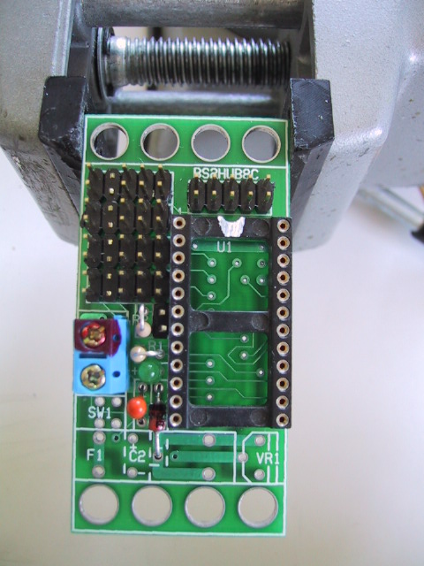
Take the small green LED and orient it
so that the long lead is on your left.
The long lead is the positive lead and
the slightly shorter lead is the negative
one. LED's are not symmetrical; if you
put them in backwards, they will not
operator properly. Insert the LED into
area marked `D1+' with the long in the
hole closest to the `+'. The negative
lead goes into the hole on the right.
As before, turn the board over, spread
the leads, solder one, verify seating,
solder the remaining lead, and snip off
excess leads.
[step9.jpg]
-
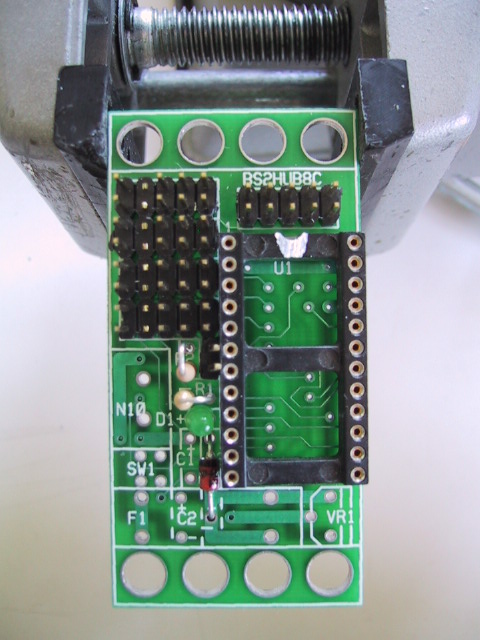
Take the remaining diode and orient it so
that the end with the circular band painted
around it is pointing up. This is diode D2.
The end with the band is negative and the
other end is positive. Diodes are not symmetric,
if it is installed backwards, the board will
not work properly. Bend both leads down by
90 degrees. Align the leads so that they go
through the two holes of D2. Insert the
positive lead into the top hole and the
negative lead into the bottom hole. Turn
the board over, spread the leads, solder one
lead, verify seating, solder the other lead,
and snip the excess leads off.
[step10.jpg]
-
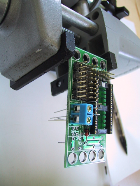
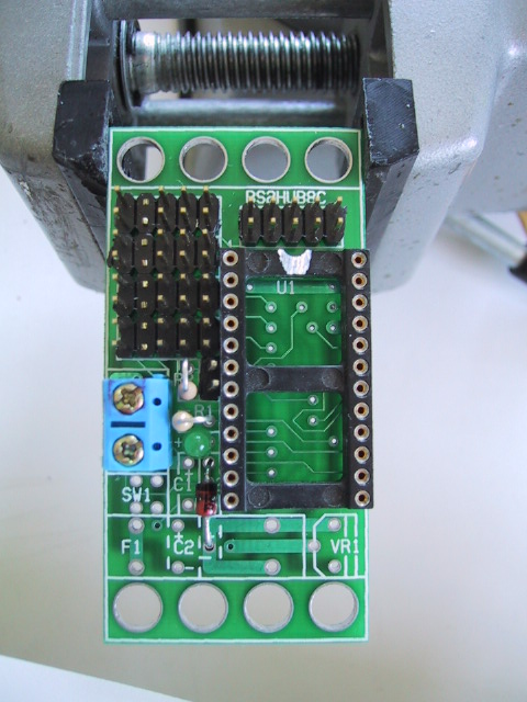
Find the two terminal blue terminal block
and orient it so that the wires will enter
the block from the left. Insert the terminal
block into the holes for N10. Turn the board
over while carefully holding the terminal
block in place. Solder one lead, verify
seating, and solder the remaining lead.
[step11.jpg,
step12.jpg]
-
Using a fine point pen carefully mark the top
terminal with a `+' and the bottom terminal
with a `-'. Some people will take a red
magic marker and mark the top most lead
as red as a way of remembering that the
positive battery lead (usually colored
red) goes into the top terminal and the
negative battery lead (usually colored
black) goes into the bottom terminal.
[step13.jpg]
-
Find the .47µF tantalum capacitor.
This is capacitor C1. Orient the capacitor
so that the lead marked with a `+' is on the
top and the lead marked with a `-' is on the
bottom. Like diodes, tantalum capacitors are
not symmetrical, if they are installed backwards,
they will not work properly. Insert the
positive lead into the top hole (i.e. the next
to the `+' sign) and the other lead into the
bottom hole. Turn the board over, spread the
leads, solder one lead, verify seating, solder
the other lead, and snip the excess leads off.
[step14.jpg]
-
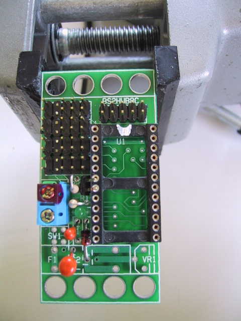
Find the 22µF tantalum capacitor.
This is capacitor C2. This capacitor is
going to be oriented on its side rather
than vertically. The reason for this is
because the fuse will be resting on top
of the C2. As in the previous instruction,
find the `+' and `-' leads and orient the
capacitor with the `+' on top. Now bend
the capacitor over on its side by 90 degrees.
Now the capacitor is pointing to the right
and leads are pointing straight down towards
the board. Put the `+' lead into the hole
labeled `+' and the `-' lead into the hole
labeled `-'. You know the drill, turn the
board over, spread the leads, solder one
lead, verify seating, solder the other
lead, and snip off the excess leads.
[step15.jpg]
-
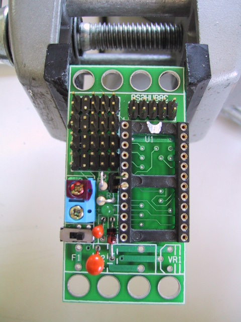
Find the little switch SW1. While the
switch is symmetrical, we need to snip
off two leads on one end in order for
it to fit in the 4 available holes.
Turn the switch over and snip off two leads
as indicated by `X's below:
Now flip the switch over so that the 4
remaining leads are on the right and insert
it into the 4 holes labeled SW1. While
holding the switch in place with your hand,
carefully turn the board over, and solder
in 1 lead. As usual, verify seating prior
to soldering in the remaining 5 leads.
[step16.jpg]
-
It is possible to install the fuse clips
backwards. To prevent this, please find
both fuse clips and snap them onto the
fuse. While the fuse is 20mm long, the
spacing for the fuse clip is closer to
25mm long. Place the whole fuse and fuse
clip assembly into the 4 holes labeled F1
on the board. There will be some additional
space between the fuse ends and the fuse
clip edges; this is OK. Remember the fuse
goes over capacitor C2, so it might be
necessary to push C2 down a little to get
everything to fit. Again, while holding
the fuse assembly in one hand, turn the
board over and solder in one lead of each
fuse clip. To prevent burns, it is a good
idea to hold the assembly by the glass fuse
rather than the metal clips. After seating
has been verified, solder the the fuse clips
all the way in.
[step17.jpg]
-
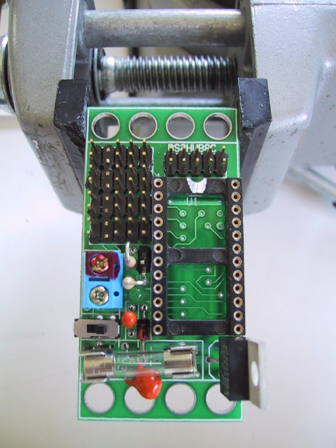
Take the LM2940 voltage regulator and orient
it so that the lettering is facing you.
The LM2940 is component VR1. Bend the middle
lead a little towards you and the two outer
leads a little away from you. Now rotate VR1
90 degrees clockwise around its vertical axis
of symmetry. Insert VR1 into the three holes
labeled VR1. Turn the board over, spread the
leads a little, solder one lead, verify seating,
solder the remaining leads, and snip off any
excess leads.
[step18.jpg,
step19.jpg]
-
Find the heat sink and orient it such that
the fins are pointing to the left with the
hole on top. Using the screw and nut, attach
the heat sink to VR1, such that VR1 is enclosed
by the heat sink.
[{Missing picture with heat sink.}]
The assembly of the BS2Hub8 (Rev. C) RoboBrick is
complete.
Copyright (c) 2002 by
Wayne C. Gramlich.
All rights reserved.