This is the construction instructions for the
AnalogIn4 (rev. D) RoboBrick. The status of this project is
work in progress.
AnalogIn4 RoboBrick (Revision D) Construction
The instruction steps for building the AnalogIn4
(Rev. D) RoboBrick are listed below:
-
Orient the board so that it is vertical.
By convention, north is the upper edge,
south is the lower edge, west is the left
edge, and east is the right edge.
N1 should be in the north west corner.
[Step 1].
-
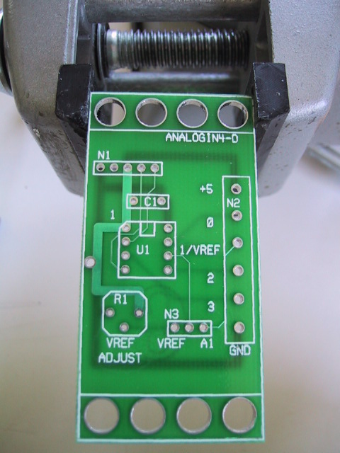
Take a 1×5 male header and using
some diagonal cutters, snip off pin 2 using
the diagram below:
Pin 2 is the pin marked with an `X'.
Install the 1×5 male header into N1
with pin 1 to the left. First, solder only
one pin and verify that the connector is
pointing straight up. If not, use the
soldering iron to melt solder around the
pin you just solder and reposition the
header so that it is pointing straight up.
When you are happy with the position,
solder in the remaining 4 pins.
[Step 2].
-
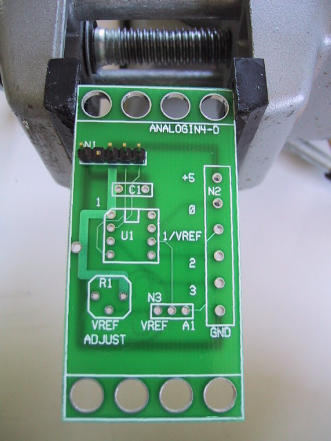
Take a 1×3 male header, orient it so
that it is horizontal, and insert it into N3.
As in the previous instruction, solder 1 pin,
verify that it is completely vertical, and
solder the remaining 2 pins in.
[Step 3].
-
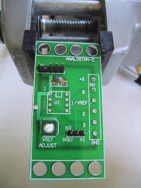
Find the 10pF capacitor and insert it into C1.
Spread the leads, solder 1 pin, verify that
it is positioned correctly, solder the remaining
lead, and snip off the excess leads.
[Step 4].
-
Find the 100K trim potentiometer and insert it
into R1. There is only one orientation where
all three leads will fit straight in. Solder
one lead, verify that it is flat on the board,
solder the remaining 2 leads, and snip off
the excess leads.
[Step 5].
-
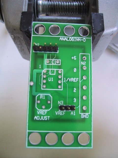
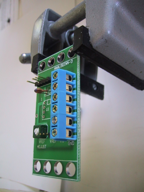
Find the 6-terminal terminal strip and insert
it into N2. If all you can find is some 2-terminal
strips, a 6-terminal strip can be assembled from
three 2-terminal strip by sliding them together.
Make sure that the wire holes point towards the
east. Solder in 1 pin, verify position, and
solder the remaining pins.
[Step 6].
-
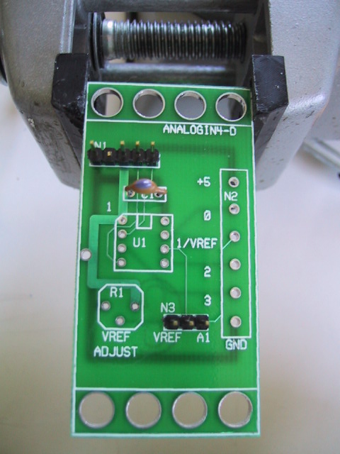
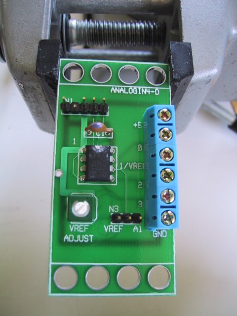
Install the preprogrammed PIC12C672 into U1
with the notch facing up. (We have highlighted
the notch in the construction picture with some
while marker.) Solder in one pin, verify that
the IC is flat against the board, re-heat and
reposition if necessary, and solder in the
remaining pins. It is very important that the
chip does not get overheated. Use a low wattage
soldering iron. Also, solder in one pin at a
time and then touch the chip with your finger;
if it is hot to touch let the chip cool down
before you solder in another pin.
[Step 7].
-
Install the shorting block on N3 on the two
pins to the east.
[{Missing step8 picture}].
The assembly of the AnalogIn4 (Rev. D) RoboBrick is
complete.
Copyright (c) 2002 by
Wayne C. Gramlich.
All rights reserved.