This is the revision A version of the WireHost module.
The WireHost module connects to both a RoboBricks2 bus and host computer via an RS-232 serial port. For computers that only have a USB port, a USB to RS-232 converter is required. The firmware in the WireHost module allows programs to be downloaded into other modules on the RoboBricks2 bus, such as one or more Controller28 modules.
In order to support long cables from the host computer to the robotic platform, the WireHost module uses inexpensive telephone cable with RJ11 connectors on both ends. The DB9RJ11 module is used to interface the RJ11 connector to a more standard female DB9 connector.
The WireHost module is connected to the host computer via 9-pin D connector using standard RS-274 voltage signalling levels (±12) running a 115200 baud with 8N1 (1 start bit, 8 data bits, No parity, and 1 stop bit.) If the host computer has a serial port, the connection can be made directly. If the host computer only has a
There are two supported modes -- terminal mode and host mode. In terminal mode, it is anticipated that the user will be talking to the WireHost module via a terminal emulator such as HyperTerminal on Windows® or MiniCom on Linux®. In host mode, it is expected that the use will be using a custom program that opens a serial connection to the WireHost module.
All terminal mode programs have the most significant bit cleared (i.e. plain ASCII) and all of the host commands start with the most significant bit set. This is summarized in the table below:
Bit Mode 7 6 5 4 3 2 1 0 0 x x x x x x x Terminal Command 1 x x x x x x x Host Command
Both terminal mode and host mode are discussed in separate sections below.
Terminal Mode supports the following commands:
Command Response Description A ii nn rr Programm the module with an id of ii set the node address nn. The response code rr is printed. C rr Send the bus clear command out. This resets all of the modules on the bus into passive mode. D rr Deselect the currently selected node. The response code rr is printed. I Indentification information Print out the identification for the currently selected node. J aaaa Jump into the code of the currently selected processor at aaaa. S nn rr Select node nn and print response rr. If no node responds, '@' is printed. X xx rr Transmit byte xx to the currently selected node. The response byte rr is printed. If no response is received, '@' is printed. P pp 16 rows of 2 byte words Print out page pp of program memory from the currently selected processor. R aaaa vv Read the byte at aaaa from the currently selected processor and display it as vv. W aaaa vv Write byte vv into memory at address aaaa of the currently selected processor. Z Identification for all modules. Sweep the bus and identify all modules plugged into the bus. :xx... Program one line of Intel hex file into currently selected processor.
When the WireHost module is in host mode it can either be in master mode or slave mode. In master mode, it is control of the bus, it can select and deselect modules, send command bytes, and receive response bytes. In slave mode, it basically just forwards command bytes to the host so it can respond.
Command
NameBit Direction Description 7 6 5 4 3 2 1 0 Transfer 0 x s s s r r r Send This transfers sss bytes to the the bus. aaaaaaaa through mmmmmmmm correspond to the sss bytes sent. All bytes are sent with the 9th bit clear, unless x is set in which case the first byte is sent with the 9th bit set and the remaining bytes are sent with the 9th bit clear. nnnnnnnn through zzzzzzzz correspond to the rrrr bytes received. a a a a a a a a Send ... Send m m m m m m m m Send n n n n n n n n Receive ... Receive z z z z z z z z Receive
There are two PIC16F688 microcontrollers on the WireHost module. One microctonroller is called the host processor since it is permanently attached to the host computer via the MAX232 RS-232 voltage level conveter. The other microcontroller is permanently attached the to RoboBricks2 bus and is called the bus processor. There are seven wires that are connected between the processors This section documents the data communication protocol between the two processors.
The seven wires between the two processors are labeled P6 through P0 as summarized in the table below:
Since the bus microcontroller needs to be able to generate a reset signal on N2, RA2 is used this purpose. Since RA2 is not avaiable for the interprocessor communciation, RA3 is used instead. The problem with RA3 is that it is an input only pin.
Label Host Pin Bus Pin Use Direction P6 RA2 RA3 Handshake Host to Bus P5 RA1 RA1 Handshake Bus to Host P4 RA0 RA0 Strobe Host to Bus P3 RC3 RC3 Data Host to Bus P2 RC2 RC2 Data Host to Bus P1 RC1 RC1 Data Bus to Host P0 RC0 RC0 Data Bus to Host
The host processor is always in controlling the data exchanges between the two processors. Basically data is extanged between the two processors two bits at a time. P3:2 are used to send data from the host processor to the bus processor. P1:0 are used to send data from the bus processor to the host processor. P4 is used to indicate that a command needs to be processed. P6:5 are used for handshaking between the two processors to synchronize data transfer.
The handshaking works as follows:
Currently there are only three commands that the host processor can issue and they are summarized in the table below:
Host Sends Bus Returns Description 9 8 7 6 5 4 3 2 1 0 9 8 7 6 5 4 3 2 1 0 0 s s s s s s s s s Send s ssss ssss out to the bus 1 0 e r r r r r r r r r Receive r rrrr rrrr from bus. e is 1 if no receive byte is present. 1 1 Strobe reset line on N3.
The hardware consists of a circuit schematic and a printed circuit board.
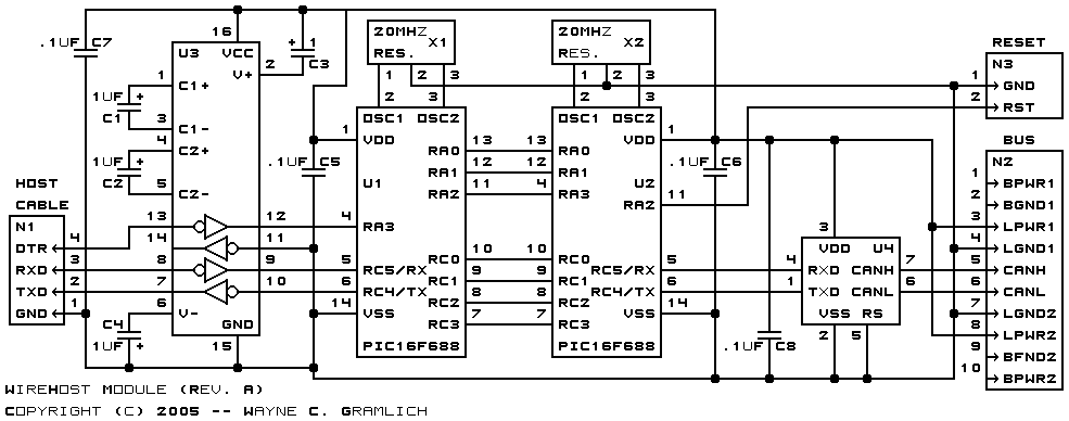
The schematic for the WireHost module is shown below:
The parts list kept in a separate file -- wirehost.ptl.
The printed circuit board files are listed below:
- wirehost_back.png
- The solder side layer.
- wirehost_front.png
- The component side layer.
- wirehost_artwork.png
- The artwork layer.
- wirehost.gbl
- The RS-274X "Gerber" back (solder side) layer.
- wirehost.gtl
- The RS-274X "Gerber" top (component side) layer.
- wirehost.gal
- The RS-274X "Gerber" artwork layer.
- wirehost.gml
- The RS-274X "Gerber" mask layer.
- wirehost.drl
- The "Excellon" NC drill file.
- wirehost.tol
- The "Excellon" tool rack file.
The cable information can be found in the DB9RJ11 Module.
There are two sets of firmware available for the Wirehost module.
The host firmware is available in the following files:
- host.ucl
- The µCL source code for the Host module.
- host.asm
- The Host module assembly code file.
- host.lst
- The Host module listing file.
- host.hex
- The µCL WireHost Intel® Hex file.
The bus firmware is available in the following files:
- bus.ucl
- The µCL source code for the Bus module.
- bus.asm
- The Bus module assembly code file.
- bus.lst
- The Bus module listing file.
- bus.hex
- The µCL WireHost Intel® Hex file.
The following fabrication issues came up: