This is the revision D version of the Sonar2 module.
This is a completely optoisolated Sonar module for driving sonar modules. The Sonar modules can be from the following list:
Command
NameBit Action Description 8 7 6 5 4 3 2 1 0 Raw Read 0 0 0 0 0 0 0 0 s Send Return the pulse length as hhhh hhhh llll llll × .2microSec. 0 h h h h h h h h Receive 0 l l l l l l l l Receive Centimeter_Read 0 0 0 0 0 0 0 1 s Send (Unimplemented) Return the distance for senosr s as dddd dddd centimeters. 0 d d d d d d d d Receive Millimeter_Read 0 0 0 0 0 0 1 0 s Send (Unimplemented) Return the distance for senosr s as dddd dddd millimeters. A return result of 1111 1111 means that the distance exceeds 254 millimeters (=10.45 inches) 0 d d d d d d d d Receive
The hardware consists of a circuit schematic and a printed circuit board.
The parts list kept in a separate file -- sonar2.ptl.
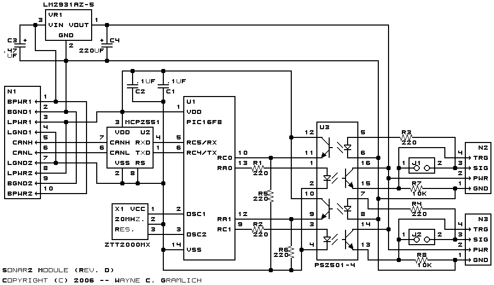
The schematic for the Sonar2 module is shown below:
The module is connected to the RoboBricks2 bus via connector N1. The signals come in on N1-5 and N1-6 and are connected through the CAN bus physical layer transceiver (MCP2551) at U2. The TX and RX pins of the microcontroller (PIC16F688) at U1 are connected to U2. To send a pulse to a servo, either U1-13 (RA0) is brought high, or U1-9 (RC1) is brought high. This causes current to flow through R1 (or R2) through the light emitting diode in the quad opto isolator (U3). This saturates the corresponding NPN transistors, which pulls R7 (or R8) to near 5 volts (4.8 volts is more like it.) This will trigger the sonar unit connected to either connector N2 or N3. Some sonar units combine the trigger and pulse back pins (e.g. Parallax Ping and Maxbotix MaxSonar-EZ1) and others keep the separate (e.g. Devantech SRF04.) For combined trigger and pulse systems, J1 (or J2) are shorted together; otherwise they are left open. The trigger pulse will cause current to flow through current limiting resistor R3 (or R4) and light up the corresponding light emmitting diode int the quad opto-isolator in U3. The corresponding transistor will saturate and pull the resistor R5 (or R6) up to 5 volts (again, it is closer to 4.8 volts) and feed the signal into U1-10 (RC0) or U1-12 (RA1).
The printed circuit board files are listed below:
The following files are available:
The following fabrication issues occured: