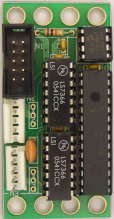
This is the revision E version of the Shaft2 module.
The Shaft2 module keeps track of two quadrature rotation sensors.
Bill Benson is providing additional Shaft2 documentation.
This module uses two shaft encoders to keep track of position and bearing using deduced (a.k.a. dead) reckoning. Everything is measured in term of "units" and "ticks". A "unit" is one unit of lenght. It is typically something fairly small such as a millimeter or a tenth of an inch. A "tick" is how many counts the quadrature encode ticks over in an entire revolution. This is typically a power of 2 such as 1024, 2048, or 4096.
In order to keep track of everything, you need to specify the distance between the wheels (in "units"), the diameter of the wheels (in "units") and the number of ticks for one wheel revolution. After that, the module can be queried for the estimated X and Y corrdinates and bearing.
In addition, it is possible to specify a taget X and Y. The module will return the bearing to the target as well as the distance to the target.
A separate programming table specifies the protocol for accessing the module functionality.
In addition, people who program in Easy-C can use an access library.
The hardware consists of a circuit schematic and a printed circuit board.
The parts list kept in a separate file -- shaft2.ptl.
The schematic for the Shaft2 module is shown below:
The printed circuit board files are listed below:
The following firmware files are available:
Any fabrication issues that come up are listed here.
The motors and shaft encoders that have been used with this module come from Solutions Cubed. In particular, the motor is the MOTOR1 and the encoder is the ENC300. The motor is available from alternate vendors such as Jameco. The encoders are actually from US Digital. The nice thing about Solutions Cubed is that they sell the motor, encoder, and encoder mounting kit all together, so there is no finger pointing if parts are missing.
The shaft encoder chip is the LS7366 from LSI Computer Systems and it is very difficult to obtain. I eventually wound up buying a tube of the chips from Gemini Electronics. When I called them I had to ask if they sold the chip, since it was not listed on their web site.
The encoders from US Digital conform to the following pin outs.
Note that the LS7366 must have a logic low voltage less than 1.0V and a logic high voltage above 3.5 volts.
Pin Usage US Digital Cable 1 Ground Brown or Black 2 Index no connection 3 A Channel Blue or Green 4 +5 Volts Red 5 B Channel Yellow