This is the revision A version of the
Shaft2 module.
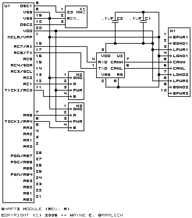
Shaft2 Module (Revision A)
The Shaft2 module keeps track of two quadrature
rotation sensors.
{Programming goes here.}
The hardware consists of a circuit schematic and
a printed circuit board.
The parts list kept in a separate file --
shaft2.ptl.
The schematic for the Shaft2 module is shown below:
The printed circuit board files are listed below:
-
shaft2_back.png
-
The solder side layer.
-
shaft2_front.png
-
The component side layer.
-
shaft2_artwork.png
-
The artwork layer.
-
shaft2.gbl
-
The RS-274X "Gerber" back (solder side) layer.
-
shaft2.gtl
-
The RS-274X "Gerber" top (component side) layer.
-
shaft2.gal
-
The RS-274X "Gerber" artwork layer.
-
shaft2.gml
-
The RS-274X "Gerber" mask layer.
-
shaft2.drl
-
The "Excellon" NC drill file.
-
shaft2.tol
-
The "Excellon" tool rack file.
The following files are available:
-
shaft2.ucl
-
The Shaft2 µCL source code file.
-
shaft2.asm
-
The Shaft2 firmware assembly
code listing.
-
shaft2.lst
-
The Shaft2 firmware listing file.
-
shaft2.hex
-
The Shaft2 firmware
Intel® Hex file.
Any fabrication issues are listed here:
Copyright © 2005-2007 by
Wayne C. Gramlich.
All rights reserved.