This is the revision A version of the MiniMotor2 module.
The MiniMotor2 module is designed to drive two small (aka mini) sized motors with a maximum current of 600 mA per motor and maximum surge current of 1.2A. The logic circuitry is electrically isolated from the motor H-bridges the via optoisolators.
{Programming will go here.}
The hardware consists of a circuit schematic and a printed circuit board. There is a separate parts list file.
The circuit schematic is broken into to diagrams. The parts list kept in a separate file -- minimotor2.ptl.
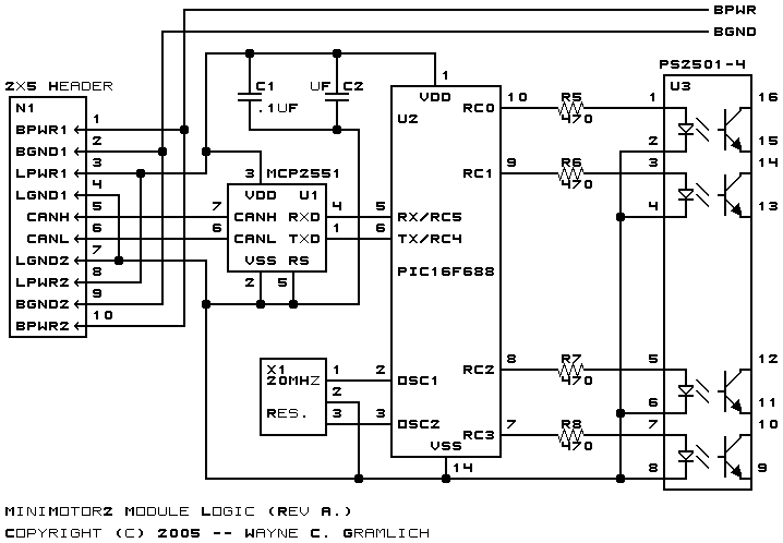
The logic section of the MiniMotor2 module is shown below:
The logic power and CAN signals come in from N1 pins 3 through 8. The CAN signals are connected to the MCP2551 CAN physical layer IC, U1. The transmit and receive pins of the microctroller, (U2 pins 5 and 6) are connected to the other side of U1. Lastly, the RC0 through RC3 are used to drive the quad optoislator, U3, through current limiting resistors R5 through R7.
Please note that U3 optoisolator shows up in both schematics. There is only one optoisolator, it is just easier to understand what is going on if the optoisolator is present in both schematics. There is no shared ground between the two sides of the optoisolator.
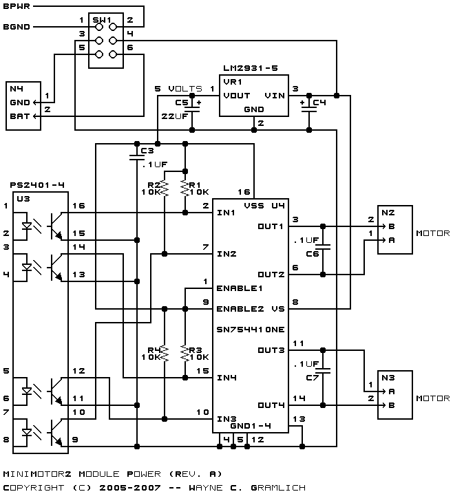
The power section of the MiniMotor2 module is shown below:
The power to drive everything can come from either an external battery at N4 or from the bus at N1. Switch S1 selects between the two possible power sources. Capacitor C3 (.1µF) and C4 (220µF) attempt to filter out any noise from the power source. The power is fed into a 5V low drop out voltage regulator (VR1) and the output is fed into C5 (22µF) to provide a stable 5V power supply for the H-bridge chip (U4). The opto-isolator chip (U3) outputs are fed to the inputs of U4 (IN1-4) to control the H-bridge. Resistors R1-4 are pull-up resistors. The enable pins for U4 are tied high. Motor 1 is connected to N2 and motor 2 is connected to N3. Capacitors C6 and C7 attempt to filter out high frequency noise coming back from the motors.
The printed circuit board files are listed below:
The following files are available:
Any fabrication issues are listed here.