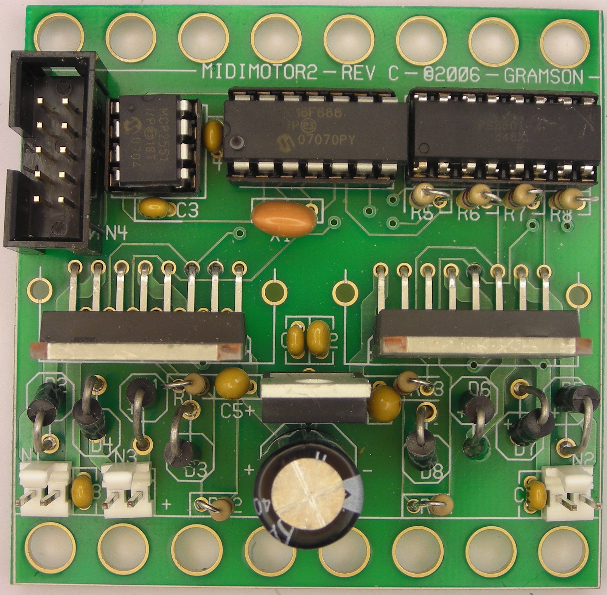
This is the revision C of the MidiMotor2 module.
The MidiMotor2 module is designed to drive to medium (aka midi) sized motors with a maximum current of 3.5 Amperes per motor. The logic circuitry is separated from the motor H-bridges via optoisolators.
Bill Benson is providing additional MidiMotor2 documentation.
Basically there are two motors that can be controled -- Motor0 and Motor1.
The speed ranges from -128 to 127. The Programming Table has all of the available programming commands. For those of you that program in Easy-C there is libarary of controller routines.The hardware consists of a circuit schematic and a printed circuit board.
There is a separate parts list file.
The logic section of the MidiMotor2 module is shown below:
The logic power and CAN signals come in from N4 pins 3 through 8. The CAN signals are connected to the MCP2551 CAN physical layer IC, U5. The transmit and receive pins of the microctroller, (U4 pins 5 and 6) are connected to the other side of U5. Lastly, the RC0 through RC3 are used to drive the quad optoislator, U3, through current limiting resistors R5 through R7.
Please note that U3 optoisolator shows up in both schematics. There is only one optoisolator, it is just easier to understand what is going on if the optoisolator is present in both schematics. There is no shared ground between the two sides of the optoisolator.
The power section of the MidiMotor2 module is shown below:
Each L298 (U1 and U2) is a dual H-bridge in a Multiwatt-15 package. As per recommended practice, the two H-bridges are ganged together to form a single H-bridge with 3.5 Amp capacity. Power comes in on N3. The dedicated regulator VR1 provides 5 volts for the logic ciruitry. The H-bridge circuitry is always enabled. The Schottky diodes (D1-D8) are used to clamp out unwanted voltage spikes that occur as a result of switching. Each H-bridge is connected to two optoisolators in U3 to allow independent switching of the H-bridge.
The printed circuit board files are listed below:
The following files are available:
Any fabrication issues will be listed here.