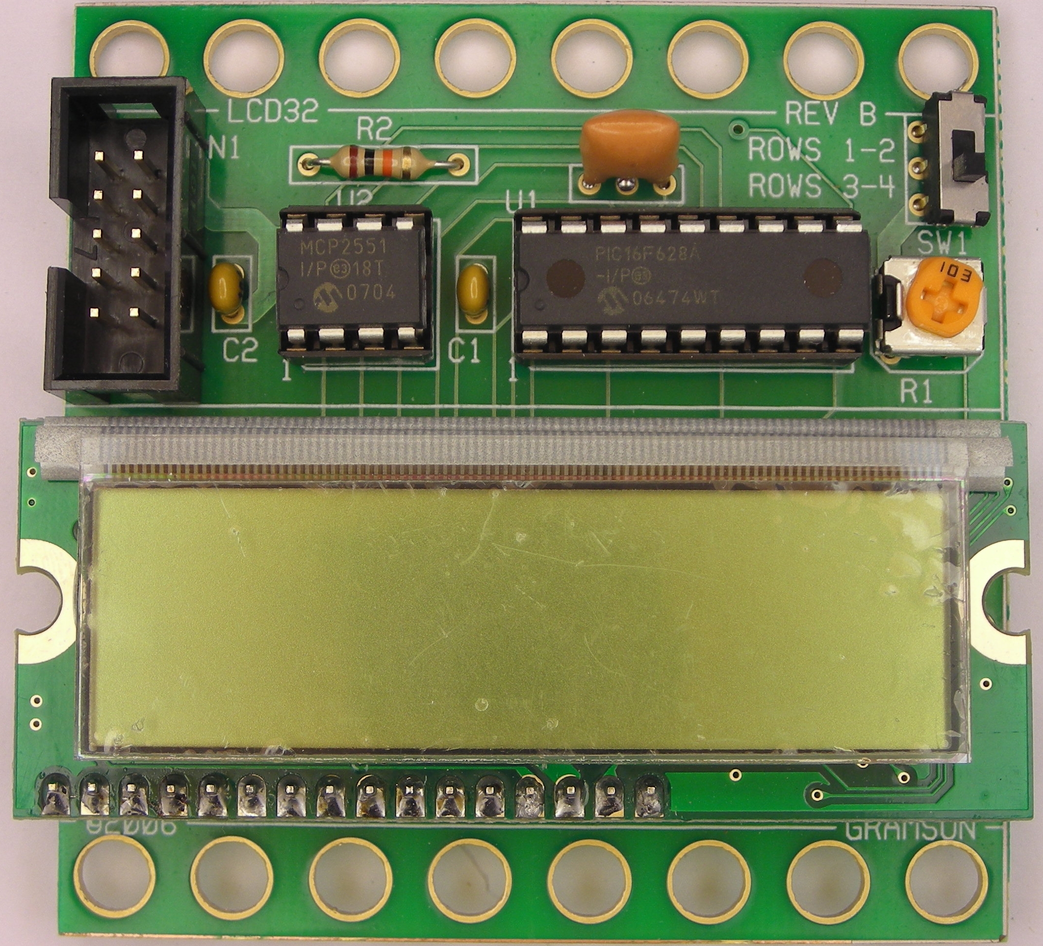
This is the Revision B version of the LCD32 module.
This document is also available in PDF format.
Bill Benson is providing additional additional LCD32 documentation.
The LCD32 module can display a total 4 lines of 16 characters each, of which only 2 lines are visible at a time. The characters are displayed using a 5×7 dot matrix. There is a mechancal switch labeled LINES on the LCD32 module that switches between displaying lines 1-2 and lines 3-4. The LCD32 module is based upon the inexpensive Lumex® LCM-S01602DTR/M 2×16 liquid crystal display (LCD) module available from both Digikey® and Mouser®. The LCD32 module has a small trim potentiometer that allows you adjust the display contrast.
There is a separate programming table for this module.
For people that program in Easy-C, there is a separate access library.
The hardware consists of a circuit schematic and a printed circuit board.
The schematic for the LCD32 RoboBrick is shown below:
The parts list kept in a separate file -- lcd32.ptl.
The printed circuit board files are listed below:
The LCD32 software is available as one of:
The follow fabrication issues occurred:
