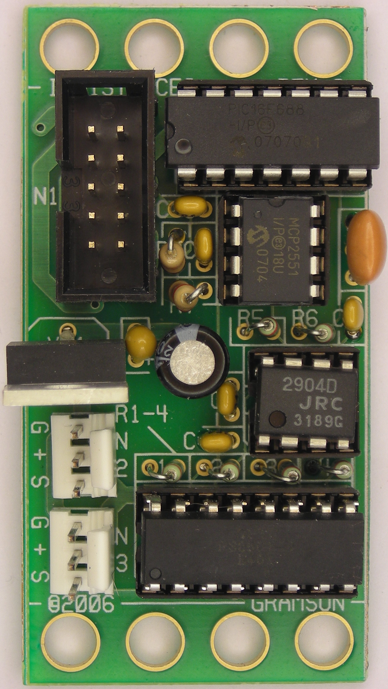
This is the revision C version of the IRDistance2 module.
The IRDistance2 module works in conjunction with up to two Sharp GP2D12 infrared optical distance measuring units to return distances in the the general vicinty of 10cm to 60cm. The module is completely optoisolated to deal with the extremely variable current draw of the module -- from 9mA to 220mA. The behavior of the Sharp sensors is documented in an article by Pete Miles in the August 2004 issue of Servo (page 24.)
Bill Benson is providing some additional IRDistance2 module documentation.
For people that program in Easy-C, there is a separate access library.
The hardware consists of a circuit schematic and a printed circuit board.
The parts list kept in a separate file -- irdistance2.ptl.
The schematic for the IRDistance2 module is shown below:
The module is connected to the RoboBricks2 bus via the 2×5 male connector N1 which feeds the can CAN bus physical layer signals into the MCP2551 (U2) which is fed into the PIC16F688 microcontroller (U1). The power draw of a GP2D12 varies between 220mA and 9mA. For this reason it is not powered off of the logic power bus. Instead, power is provided by the battery power bus which is electrically isolated from the logic power. The battery power bus is fed into the low drop out voltage regulator VR1 with regulation capacitors C1 and C2.
Since there are two identical circuits for reflecting the analog voltage from a GD2D12 over to an A/D pin on the microcontroller, only one of the circuits is discussed in detail. Thus, only the signal path from N2 pin 1 through to U1 pin 8 is discussed below.
The input signal comes in on N2 pin 1 and is fed to the positive input of the op amp, U4 pin 3 and causes the output (pin 1) to rise and start pumping current into LED's on pins 1-4 of U3. As the LED on pins 1 and 2 of U3 illuminates the base of the phototransistor on pins 15 and 16 of U3, a current is developed and voltage starts to develop across the 240 Ohm resistor R3 connected to the negative input of op amp U4 pin 2. Eventually, the circuit stablizes to the point where voltage across R3 equals the input signal.
The same current that is illuminating the LED on pins 1 and 2 of U3 is also flowing through the LED on pins 3 and 4. Since the current is the same, the illumination on the base of the photo transistor on pins 13 and 14 is the same. This causes the same current that is flowing through the photo transistor to be produced. Since R5 has the same resistance as R3, the same voltage is produced across R5 as is produced across R3. This voltage is fed into A/D channel 5 on pin 9 of the microcontroller U1. Thus, VN2 = VR3 = VR5
I would like to acknowledge that the circuit above was provided to me by David Wyland after my original circuit did not work worth a darn. Thanks!
The printed circuit board files are listed below:
The following files are available:
The following test program is available:
Any fabrication issues will be listed here:
