This is the revision A version of the Ether1 module.
The Ether1 module provides an interface for connecting between an Ethernet 10BaseT ethernet connection and the RoboBricks2 bus. It can use either a 28-pin PIC (e.g. PIC16F876A) or a 28-pin AVR (e.g. ATmega168) to control the ethernet chip (Microchip MCP ENC28J60.)
No programming yet.
The hardware consists of a circuit schematic and a printed circuit board.
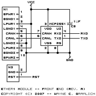
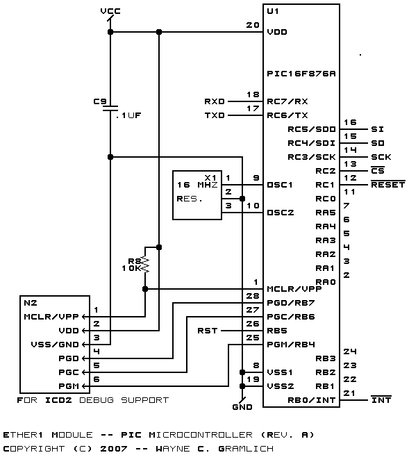
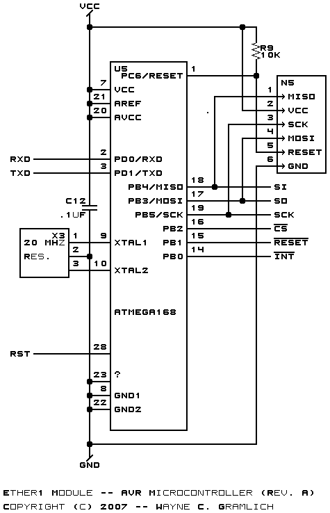
The schematic for the Ether1 module is broken into four pieces -- front end, pic, avr, and backend.
The front end schematic is shown below:
The Microchip PIC microcontroller schematic is shown below:
The Atmel AVR microcontroller schematic is shown below:
The Ethernet back end schematic is shown below:
The parts list kept in a separate file -- ether1.ptl.
The printed circuit board files are listed below:
- ether1_back.png
- The solder side layer.
- ether1_front.png
- The component side layer.
- ether1_artwork.png
- The artwork layer.
- ether1.gbl
- The RS-274X "Gerber" back (solder side) layer.
- ether1.gtl
- The RS-274X "Gerber" top (component side) layer.
- ether1.gal
- The RS-274X "Gerber" artwork layer.
- ether1.gml
- The RS-274X "Gerber" mask layer.
- ether1.drl
- The "Excellon" NC drill file.
- ether1.tol
- The "Excellon" tool rack file.
No firmeware yet.
Any fabrication issues are listed here.