This is the revision A version of the DB9RJ11 module.
The DB9RJ11 module intefaces an RJ11 connector to a DB9 connector. It is meant to used with a WireHost Module.
The hardware consists of a circuit schematic and a printed circuit board.
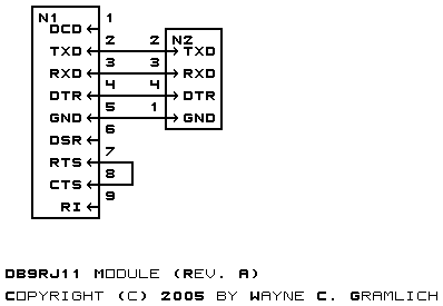
The schematic for the DB9RJ11 module is shown below:
This board is designed to eventually support the Parallax product line. Besides the required three lines T×D, R×D, and Ground, the DTR signal is on the line as well. The Parallax products use the DTR line to reset the the various Basic Stamp processors. RTS is fed back to CTS just in case the host processor has hardware flow control turned on.
The parts list kept in a separate file -- db9rj11.ptl.
The printed circuit board files are listed below:
Any fabrication issues are listed here.