This is the C revision of my
model speed control project and its current state is
work in progress.
Model Railroad Speed Control (Revision C)
At this point in time, the revision C schematic
consists of a scanned in schematic:

If you can read and understand the scanned in
schematic -- more power to you. Over time the
scanned in schematic will be transfered over to
on-line schematics below. For now these are just
the revision B schematics.
The following diagrams exist:
-
Block Diagram
-
The block diagram of the entire circuit
(no change from revision B):

-
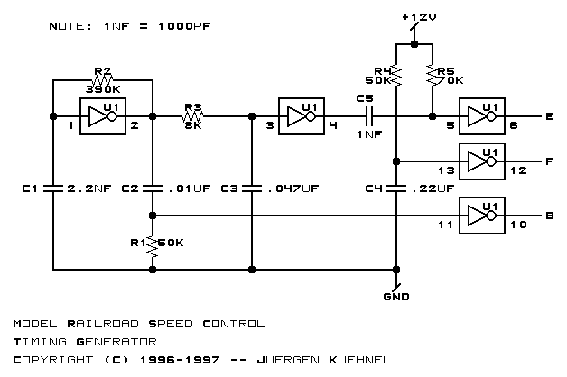
Timing Circuit
-
The timing pulse generator
(no change from revision B):
-
Power Drive
-
The power driver circuitry:
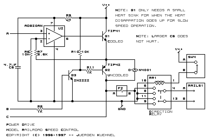
Only minor changes are coming here.
We're switch from TIP41 and TIP42 transistors
to TIP31 and TIP32 transistors. One of the
traces is being rerouted to simplify the
PCB layout. The fuse is being moved next
to the power input. Also, we're ditching
the relay because we figure people who really
want to control the direction with a relay
will put the relay off board. Lastly, we'll
be adding a capacitor to smooth out the
signal a little and a diode to clamp the
negative voltage spikes.
-
Control Amplifier
-
The control amplifier circuitry:
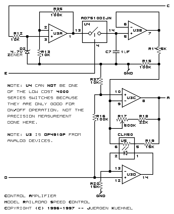
There are two major changes here. First,
we're going to switch over to a cheaper
analog switch -- the CD14016. The CD14016
is not as good as the AD7510, but it is
much more available. We will compensate
for the poorer quality of the CD14016 by
putting three of them is series to reduce
resistive losses.
The next major change is that we are replacing
the CLM50 with an opto-isolated MOSFET --
something like the H11F1QT (that may just
be a Digikey part number.) The CLM50 works
fine, but it is difficult to obtain. We
wanted something that is likely to be available
for a while.
-
Linear Momentum
-
The linear momentum control:
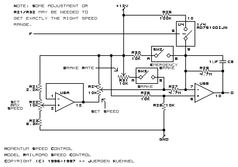
The linear momentum circuit is getting a
simple switch to enable and disable momentum.
The amount of momentum will be settable via
a potentiometer. We're giving up on the standard
brake for now. The emergency brake will remain
for a while.
-
Manual Setting
-
The manual setting stuff has been removed for
revision C.
-
Power Supply
-
The power supply:
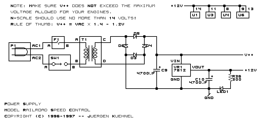
The power supply is getting more room for
the filter capacitor. The protection fuse
is going right after the diode bridge.
There is no PCB artwork yet.
Copyright (c) 1996-98 by
Wayne C. Gramlich All rights reserved.


