This is just one of several
personal manufacturing projects that is
work in progress.

Computer Numerical Controlled Mill/Lathe
Introduction
Sometime back in the mid 1970's, I purchased a
small Craftsman® lathe with vertical
milling column from
Sears®. While Sears has long
since stopped selling this particlar product,
the original manufacturer,
Sherline, continues to market and support
this product. While there have been numerous
product improvements over the years, the new
products continue to interoperate with the orignals.
Frankly, I was pretty lucky.
Back when I originally bought the mill and lathe,
I always had a dream that one day I would convert
them over to CNC (Computer Numerical Control.)
These days there are a number of companies that
specialize in
CNC Conversion of Sherline Mills and Lathes.
Indeed, Sherline now sells
CNC ready mills and lathes to make the whole
process easier.
While I could just by one of the more popular CNC
conversion kits from an outfit like
FlashCut or
Hobby CNC, that is not my style. Instead,
I tend to do things my own way.
What I intend to do is to start with a
a modular stepper motor controller that I developed
a couple of years ago. While I am not too thrilled
with how that particular project turned out, the stuff
does work, so I will work with it for now. Next, I will
take some 20 year old 65 oz.-in., 5V, 200 steps per
revolution stepper motors and attach them to the
lathe/mill along with some limit switches. Finally,
I will modify my
HobECAD hobbiest electronic computer aided design
software so that it can drive the mill to do printed
circuit board milling.
Printed circuit board milling is the process were a
blank copper cladded printed circuit board is attached
to mill table and the software drills all the component
holes and mills out the outlines of each circuit trace.
While PCB milling is not as good as shipping the board
design off to a rapid turn-around printed circuit board
manufacturer (like
Alberta Printed Circuits), PCB milling has faster
turn around and costs less. The main draw back with
PCB milling is that the holes are not plated through.
An example of how far PCB milling has progressed can
be found at
LPKF where they have developed technology that is
capable of putting up to
five signal traces between component pins separated by
.1 inches!!! I will be quite happy if I can get
a single signal trace between pins that are separated
by .1 inches.
The remaining sections of this document describe the
steps taken perform the conversion.
Setting up the Mill
My Sherline lathe is currently closest to the
Sherline Model 4000 lathe shown immediately
below:

In addition, I have the
Vertical Milling Column attachment shown
immediately below:

Most people eventually break down and purchase some
sort of base for their vertical milling column
such as the
Sherline XY Base shown below:

Again, I like to be different. Instead, of buying an
XY base, I will just use the lathe bed instead.
However, there is one major problem with using the
lathe bed; namely, the crosslide table is only about
3.5 inches long which is very restrictive. The
XY table has an `X' table length that is is 9
inches long. My solution to this problem is to
remove a the crosslide table and replace it with
a 9 inch table from the XY table via individual
replacement parts. The parts I need are:
| Part No. |
Fig. No. |
Description |
Price ($US) |
|
| 50180 |
95 |
Mill Table |
$55.00 |
| 50170 |
89 |
X Leadscrew (English) |
$12.00 |
If you look carefully, you can pick these parts
out of the fuzzy exploded view diagram below:

By the way, the figure numbers are my best attempt
at reading the numbers off the figure, they could be
wrong. I ordered the parts by directly from Sherline
via the 800 number I got off the
main Sherline web page. I will be reusing the
handwheel and thrust plate from the crosslide table.
The prices were obtained from the
replacement parts list. I figured that spending
$67 plus shipping and tax was cheaper than buying a
whole XY base for $230 (price taken from the
accessory price list.)
Another issue with the Sherline mill is that it does
not have a great deal of overhang (or throat.) The
standard vertical milling column only provides 2.25
inches of overhang. The standard solution to this
problem is to get a
mill spacer block (part number 1297) that adds an
additional 1.25 inches to the overhang. It may be
possible to stack a two or three of these things on
top of one another, but for starters I will only use
one. According to the
accessory price list, the mill spacer block
sells for $40. With one mill spacer block, I will
be able to fairly easily mill PCB boards that are
around 3.5 inches wide. If I am willing to do some
board flipping, I might be able to successfully
mill boards that are 7 inches wide. Since most of
my projects can easily be fit on a 3.5 inch wide
board, I am not anticipating any real problems in
the overhang department.
Attaching the Stepper Motors
The stepper motors I am using were purchased on
the surplus market in the early 1980's. Luckily,
stepper motors can be purchased new from outfits
such as
JameCo or
Digikey. Surplus stepper motors are available
from numerous surplus outfits like
Herbach and Redeman and
All Electronics.
When purchasing a stepper motor there are a number
of issues to consider:
-
Step Angle
-
The step angle is the resolution at which
the stepper motor naturally steps at.
100 steps/revolution works out to 1.8
degress per step; similarly 200 steps
per revolution works out to .9 degrees
per step. Multiply the lead screw
pitch by the steps per revolution
gives you the basic accuracy of the
system. For example, the Sherline
has a lead screw of 20 revolutions per
inch and my stepper motors are 200
steps per revolution, yielding 4000
steps per inch (or .00025 inch/step.)
There are some tricks called half stepping
and micro stepping that can increase
the positional accuracy of a stepper
motor.
-
Single/Dual Shaft
-
A dual shaft stepper motor has a shaft
coming out of both ends. Obviously,
a single shaft stepper motor has only
one shaft coming out of it. Dual shaft
stepper motors allow you to attach your
hand wheels to the other shaft so that
you can operate your mill/lathe manually
as well as under computer control. The
single shaft stepper motors will mandate
computer only operation (unless you make
them easy to remove.)
-
Torque
-
Torque is typically measured in units
of oz-in (ounce-inch) or gm-cm
(gram-centimeter). Technically, gm-cm
should be written as gf-cm
(grams-force-centimeter), but you will
see it written on the specification
sheets as gm-cm. In general, the more
torque your stepper motor has the better.
My stepper motors are 65 oz-in; hopefully
they will be powerful enough. There is
this trick called half-stepping that can
be used to almost double your torque.
-
Unipolar/Bipolar
-
Unipolar stepper motors have four distinct
electical coils per motor and bipolar stepper
motors have two electrical coils per motor.
In general, unipolar motors are easier to
drive electrically than bipolar motors which
require something called an H-bridge for each
coil. However, the ready availability of
integrated H-Bridge integrated circuits such
as the L293 and the L298 have made this issue
much less important than it used to be.
-
Current, Voltage, Resistance, & Inductance
-
The relation between current, voltage,
resisteance and inductance can get pretty
complicated. For stepper motors, the
maximum current is probably what you have
to worry the most about. The maximum
holding voltage is computed by mulitiplying
the coil resistance by the maximum current.
Please note that you can let the voltage
exceed the maximum holding voltage as long
as you have some circuitry in place to
ensure that the maxmium current is not
exceeded.
Stepper motors can be operated in three modes:
-
Single Step Mode
-
In single step mode, one coil at a time
is energized. This is the simplest mode
to use.
-
Half Step Mode
-
In half step mode, two coils at a time
are engergized simultaneiously to cause
the motor shaft to position itself between
the two steps. In half stepping mode, the
angular resolution is increased by a factor
two. First one coil is energize, then two,
then one, then two, etc.
-
Double Torque Mode
-
In double torque mode, two coils are always
energized to ensure that twice as much
torque is being applied to the motor shaft.
The additional torque comes at the expense
of requiring twice the power over single
step mode.
After much experimentation, I discovered that my Z
axis motor needed to be run in double torque mode
and the X and Y axes worked fine in single step
mode.
As I was converting my mill over to CNC I took
pictures of most of the steps. The mill was
converted to CNC via the following steps:
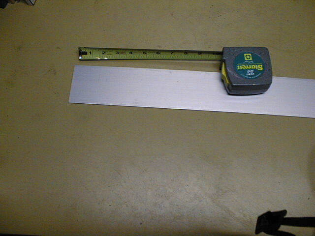
-
First I started with some
3" × 1/8" flat aluminum stock.
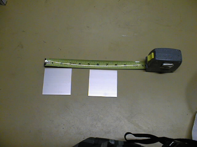
-
Next, I cut some
3" × 3" squares off the stock.
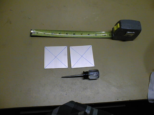
-
Next, I found the center of each square by
drawing two diagonal lines from each corner
to create an `X' that indicates the
center of the squares. I used an awl
a hammer to punch a starter mark.
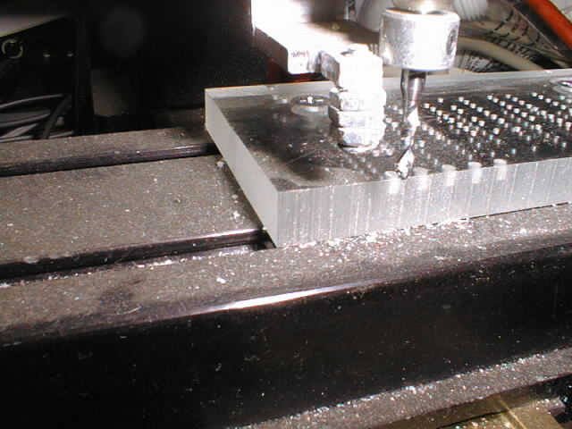
-
Using a 1/4" drill, I drilled a
hole in the center of each square for the
stepper motor shaft.
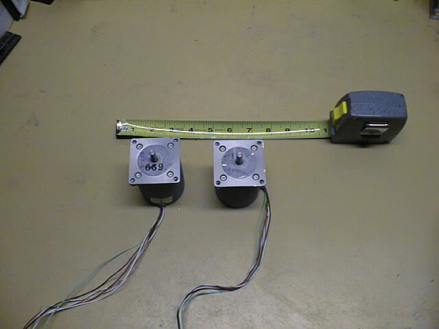
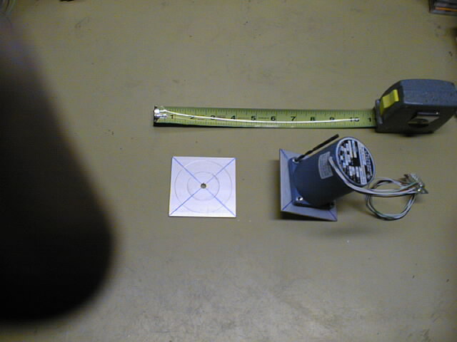
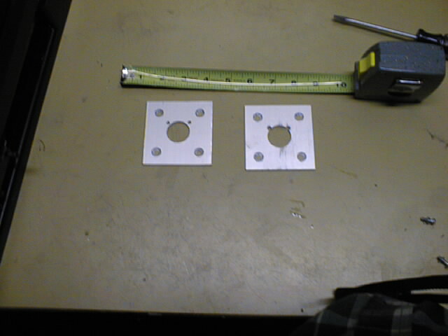
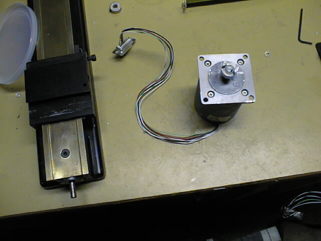
-
For, fun I just took a picture of the
stepper motors. The tape measure is there
just to give an idea of how big the motors are.
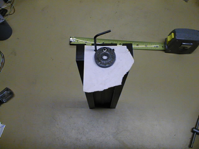
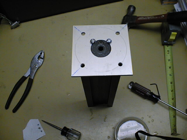
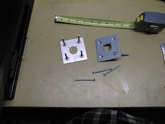
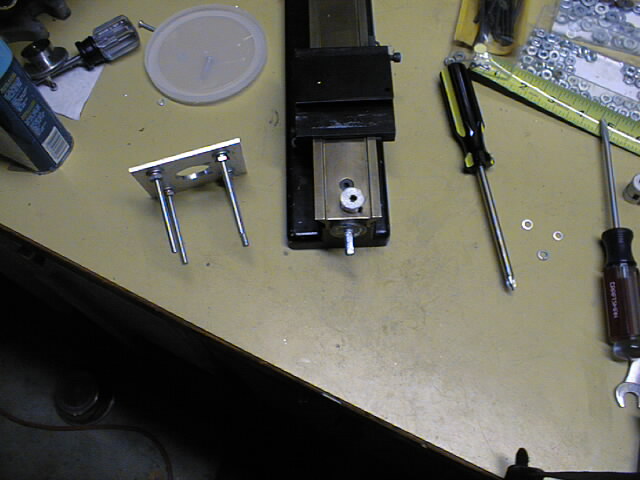
-
Next, I stuck the shaft of the stepper motor
through the square plate. Then I stuck a
sharp drill bit that just barely fit through
one of the mounting holes. Then, I twisted
the whole motor around by 360 °ree; to
scribe a circle where the mounting holes
intersect the diagonal lines. The square on
left has been scribed and the one on right is
about to be scribed. You can see the drill
bit sticking out of the mounting hole. (Yup,
that's my finger partially obscuring the
picture; nothing but the highest quality
pictures here.)
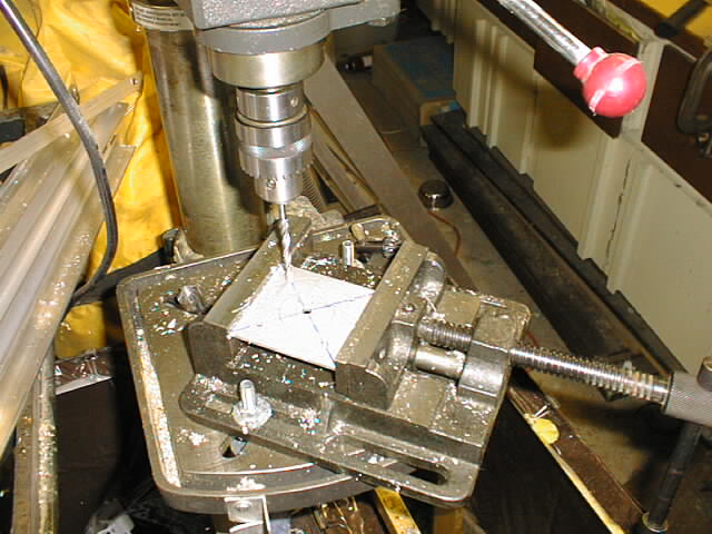
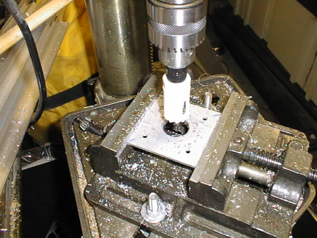
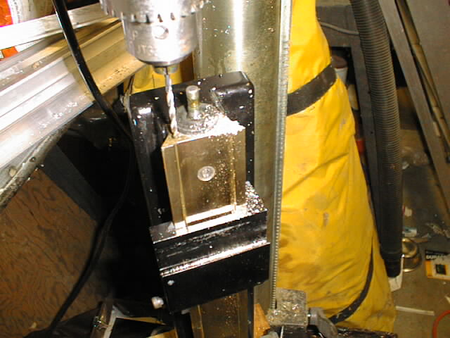
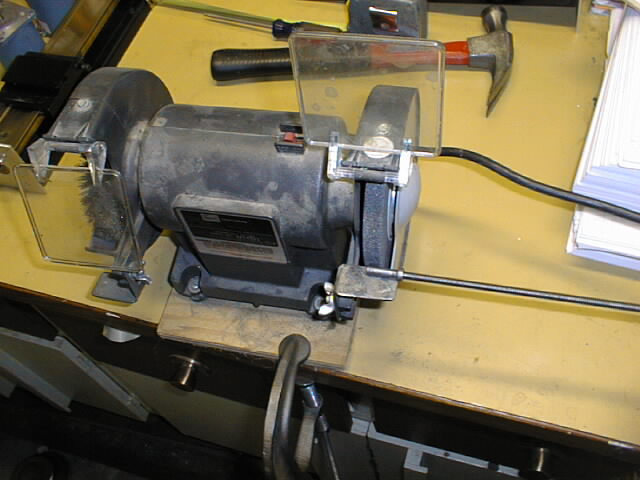
-
Next, I took my hammer and awl and punched
four starter marks where the scribed circle
crossed the diagonal lines. Then I mounted
them in my drill vise and
drilled four holes in each square.
I used the same drill that I used to scribe
the circles in the previous step.
(Normally, my drill vise is just sitting
on top of the drill press table, but my
previous operation had the vise bolted
down, so I just left it bolted to the
drill press table.)
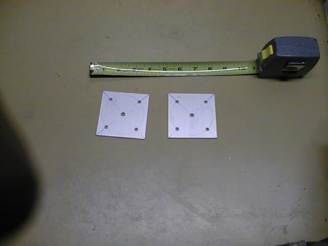
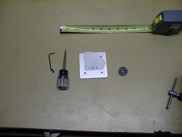
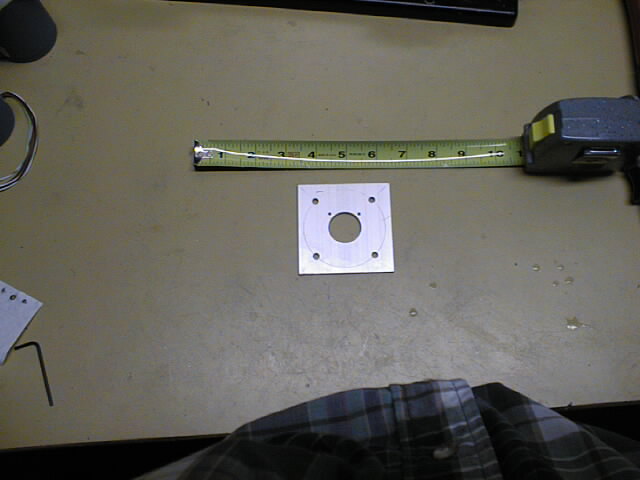
-
I removed the squares from the vise
and deburred the holes. The resulting
squares with five holes in them
are visible in the picture (along with
my fat finger over the lens again.)
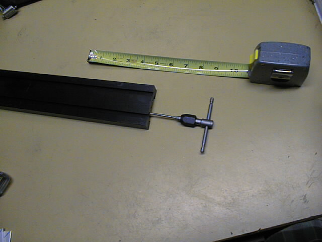
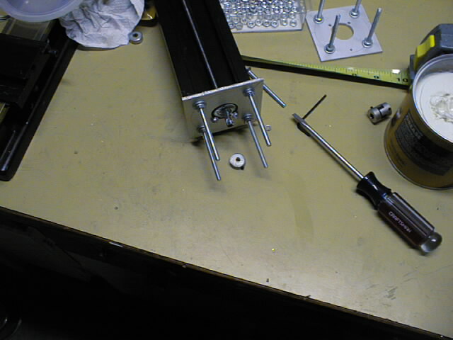
-
The Z axis table comes with two holes
predrilled in for attaching CNC adaptors.
The
two holes were threaded with a #8/24
threading tap. (I think it was #8/24.)
-
Using a random piece of paper, I attached
the thrust plate using a hex hollow head
screw. I used the end of the Allen wrench
to poke two holes to
form a drill template. I should have
also drawn a circle in the middle where the
stepper motor shaft would go. (You can
also see that my work bench is starting to
get a little cluttered.)
-
Using the paper template from the previous
step and a hammer and awl, I
marked the positions for the 2 holes to
drill.
-
Next, I drilled the two holes and
mounted the X axis plate with a couple
of #8/24 round head machine screws.
-
The next step is I got one of those bimetal
circular hole cutting drill bits that are
rated for cutting through nails. Using a
1" diameter cutting bit and plenty of cutting
fluid (I use WD-40),
I cut out a 1 inch circular hole.
(That was fun.)
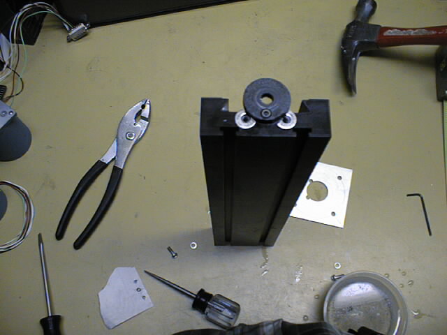
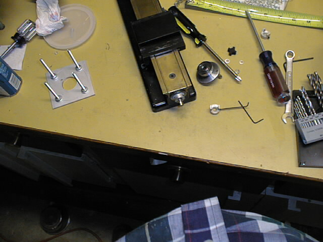
-
Since the thrust plate is thicker than my 1/8"
square plate, I needed some shims to get the
surface of the square plate up above the the
surface of the thrust plate. The shim are just
a couple of flat washers that I ground the ends
off using a bench grinder and a pair of pliers.
The picture shows the
X axis before the adaptor plate is attached.
-
Next, I just
attached the adaptor plate on top of the
shims using a couple of round head screws.
Later on, I discovered that I couldn't access
the screws, so I switched over to hex hollow
head screws that could be tightened using an
Allen wrench.
-
Now, I switched over to the Y and Z axes.
Since, the Y and Z axes are basically the
same, I'm only showing the Y axis being
worked on. (Frankly, I forgot to take
pictures of the Z axis modification.)
Using the bimetal circular hole cutting
attachment (and plenty of cutting fluid),
I cut a
1" diameter hole.
in the Y axis adaptor plate.
-
Next, I
drilled two mounting holes into the Y axis
mounting plate right near the edge of the 1"
circular hole. I decided to drill the
mounting holes to take #6 machine screws.
-
Using the Y axis adaptor plate as a template
I marked both holes with a hammer and awl.
Mounting the Y axis (i.e. the lathe bed)
in the drill press vise,
I drilled two screw holes in the Y axis.
-
Using a thread cutting tap, I
threaded both holes to take #6/32 machine
screws.
-
Next, I
mounted the Y adaptor plate. Initially,
I used round head machine screws, but later
on I switched over to hex hollow head screws
so I could access them with an Allen wrench.
-
Now I needed a 1/4" shaft collar. I visited
all the local hardware stores and there were
no 1/4" shaft collars to be found. Eventually,
I got the bright idea of
converting a shaft coupler to a shaft collar.
This is delicate operation is performed by taking
a hack saw and cutting off the two coupler
sleeves.
-
Using a bench grinder, I
ground a flat into the X axis lead screw.
The flat provides a nice flat surface for the
collar set screw to attach to.
-
Next, I took the Y-axis and
ground a flat into it as well.
-
Now, I used a counter sink bit and the
drill press to
drill out four countersunk holes in the
adaptor plates. Note I had to detach the
adaptor plates from the X and Y axes in order
to do this operation.
-
Using some 2-1/2" #8 flat head machine screws,
some washsers, lock washers, and hex nuts, I
installed the standoff screws.
-
Now the
X adaptor plate is reinstalled on the
X axis. In these pictures, I'm still using
the round head machine screws; they get changed
to hex hollow head screws later on. In addition,
one smooth side of the 1/4" shaft collar is
greased up. Notice the huge can of grease; it
was the smallest amount I could buy; I suspect
that it will last several life times.
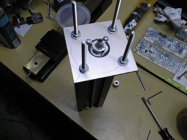
-
The
1/4" shaft collar is installed and
tightened using a small Allen wrench.
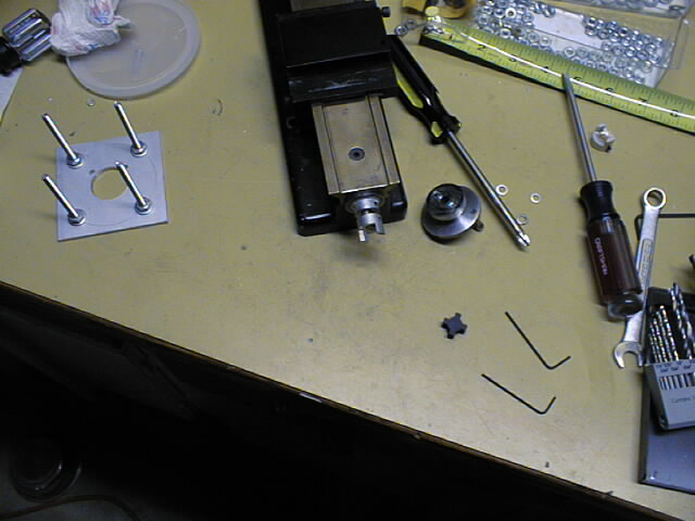
-
The
1/4" shaft coupler is installed next
and tightened using a small Allen wrench.
That black cross like thing is the torque
adaptor the fits between the two shaft
couplers.
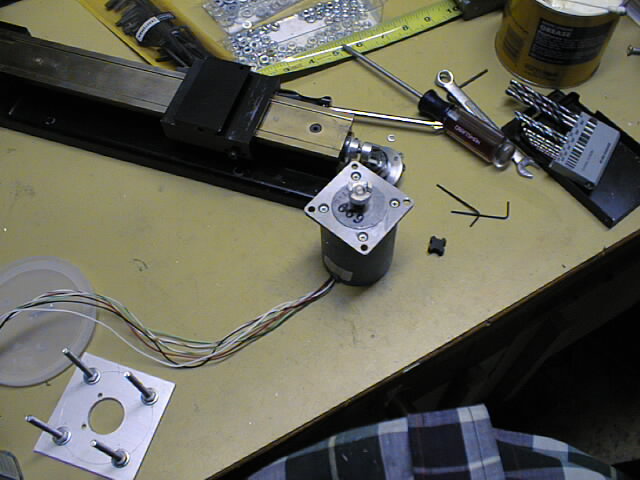
-
Next, I ground a flat into the stepper
motor shafts using a bench grinder.
A
1/4" shaft coupler is installed on
the stepper motor shaft and tightened
using a small Allen wrench.
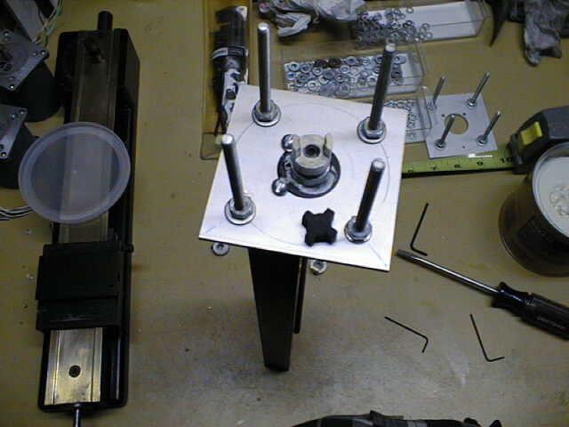
-
The torque adaptor is inserted and some
nuts, lock washers, and regular washers
are
twirled onto the standoff srews.
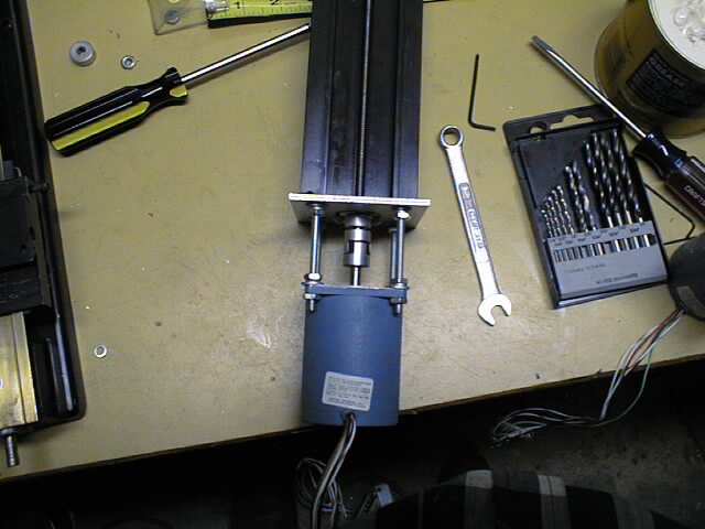
-
Finally, the stepper motor is slipped on
top of all of this and the
two shaft couplers are mated.
some additional hex nuts are twirled down
and everything is tightened up using a
hex wrench. The X axis is now ready for
some CNC machining action.
-
Switching over to the Y axis,
the 1/4" shaft collar is greased up.
-
Now,
the 1/4" shaft collar is installed and
tightened with a small Allen wrench.
-
Next,
a 1/4" shaft coupler is installed and
tightened with a small Allen wrench.
-
Now,
a 1/4" shaft coupler is installed on the
stepper motor shaft and tightened with a small
Allen wrench.
-
{Adaptor plate is installed.}
-
{Stepper motor is attached. Done.}
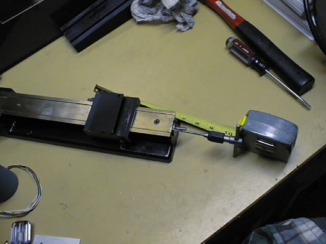
I have taken some pictures of my current floating
Z head technology:
-
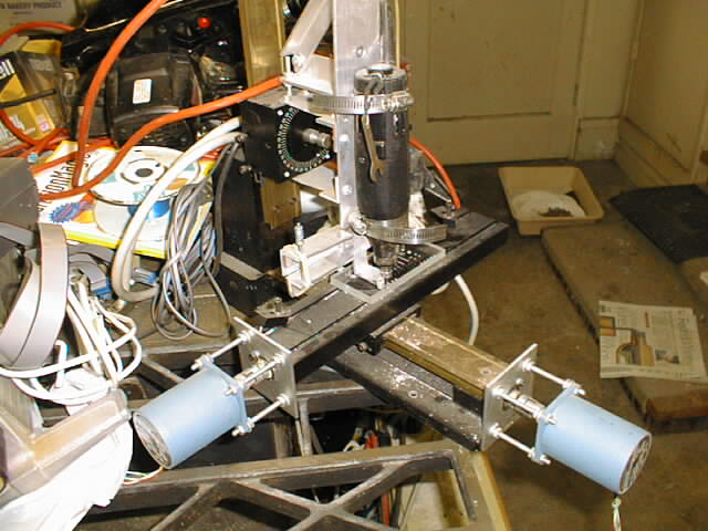
The overview picture shows the entire CNC mill
with the
floating Z head attached. Sorry, about all
the additional clutter in the picture.
-
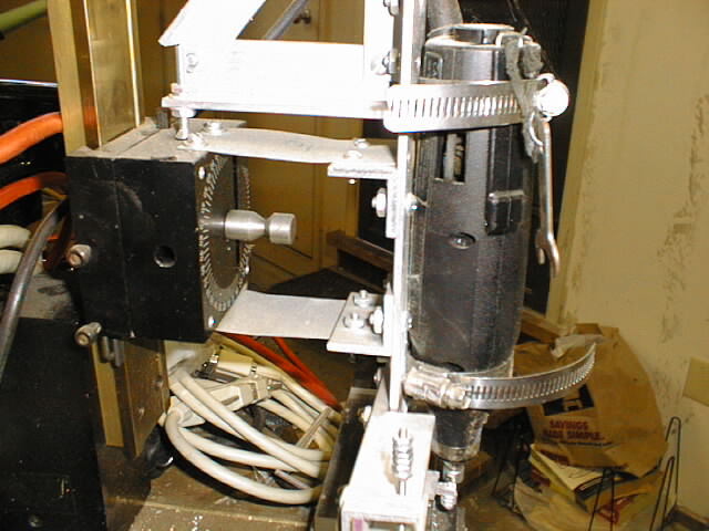
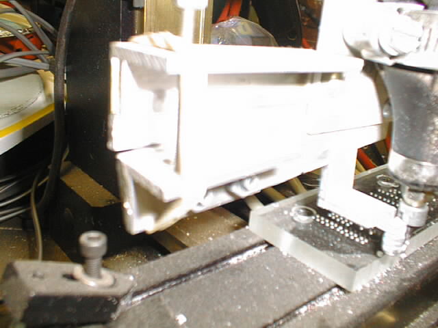
The next picture is a
little closer and shows the spacer block
attached to the vertical column. Two flexible
pieces of sheet metal are attached from the
spacer block to the spindle assembly. The
triangular thing on top is use to ensure that
the hole spindle goes up when the Z-axis goes
up. The screw on the left adjusts when the
Z-axis up movement will engage. A Dremel
® provides the spindle.
-
A round head screw that has been ground slightly
concave provides the
footpad where the floating Z head touches the
printed circuit board. A few nuts and lock washers
keep the footpad from vibrating loose. Note that
a collar has been attached to the mechanical etching
bit to help remember how far the shank goes into
the collet.
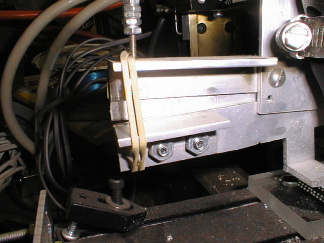
-
The
depth of cut adjustment device is held
together with a rubber band (it works!)
The end of the screw has been ground into
a point, that keeps in in a small depression.
Since the screw has a fine pitch and it is
quite a distance from the pivot, a small
movement by the screw causes an even smaller
movement by the footpad. A bunch of nuts
held together by lock washers provide a
more comfortable grip to twist the adjustment
screw. There is
washed out image from a different view
point and
another.
-
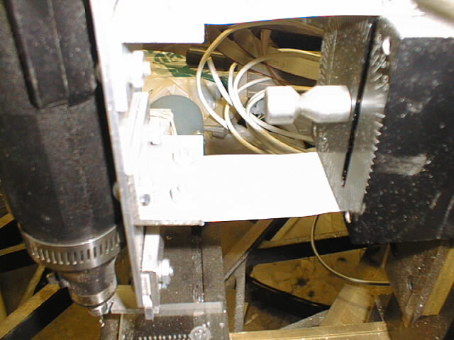
A washed out image of the
angle aluminum attach points and one that is
less washed out show how the metal flexors
attach to the spindle body. Some radiator
hose clamps are used to attach the Dremel
®.
-
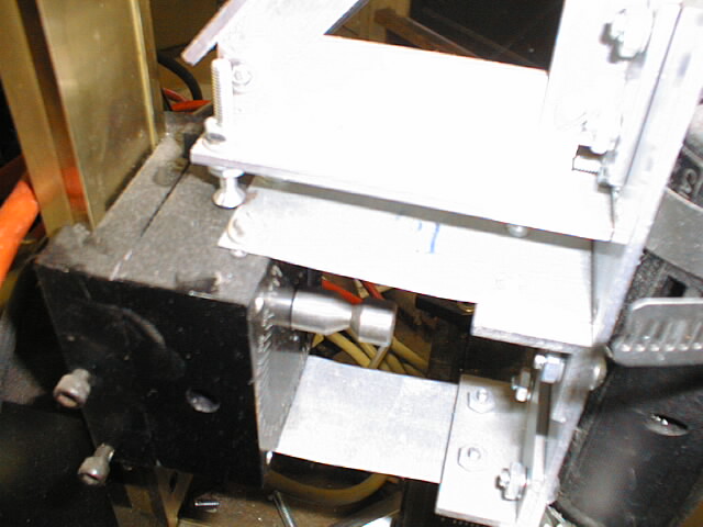
The
triangular Z stop is used to force the
spindle to move upwards when the Z axis is
moved up on computer control. The screw on
the left is used to control when the spindle
is forced up.
Copyright (c) 1995, 2000-2001 by
Wayne C. Gramlich All rights reserved.