This is just some FunCAD documentation that I am working on. This project is work in progress.
FunCAD is a computer aided design system. It currently runs on Linux and should be relatively easy to port to both Windows and MacOS.
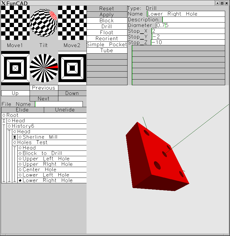
The screenshot below shows FunCAD in action:
The long term plan is for FunCAD is that it will support both mechanical and electrical computer aided design. The reason why the two are combined is because many systems contain both electrical and mechanical assemblies and they interact with one another. For example, the chasis for an electrical project needs to have holes cut for the electrical connectors. A little more subtle issue is that when laying out a printed circuit board, it is extremely desirable to see how the electrical components fit togther on the board before fabrication. The initial version of FunCAD will focus more on the mechanical side of things at first.
For mechanical CAD, the concept behind FunCAD is that it simulates the overall manufacturing of individual parts. In general, you start with a block or cylinder of raw material and use your mill and lathe to remove material. The whole process is described in terms of operations like drill a hole, mill a pocket, flip the part over, etc. It is extremeley unlikely that I am the first person to think of this. Indeed, it probably has some well known name in the CAD/CAM field that I am unaware of. Further, in the US, there is probably some ridiculously broad patent that has been issued that covers it. Sigh.
Each operation is given a unique name. The user selects from a menu of possible operations. Each operation needs some pararmeters. For example, the rectangular pocket operation to specify two 3D points that are diagonally opposite from on one another (e.g. (1.0, 1.0, .35) to (3.0, 2.0, .50)). Below is a textual representation of what kind of parameters are available:
Name: Pocket_2 Tool: End_Mill_1 X1 := 1.0 Y1 := 1.0 Z1 := .35 X2 := 3.0 Y2 := 2.0 Z2 := .50
Besides being able to type in numbers, you can also type in expressions. The expressions can contain other numbers and values defined from previous operations. For example, "Pocket_2.Z2" refers to the value in the Z2 field of the Pocket2 operation. "Pocket_1.Z1 + .3" is an example expression. Just like a spreadsheet, if the user modifies an expression, the entire design is recomputed from that point forward.
For the rectangular pocket, the user does not have to specify the depth of cut, the feedrate, number of passes, etc. The software computes all of this from the end mill dimensions, number of flutes, matrerial characteristics, machine tool charactistics, etc. The ultimate goals is that a user can manufacture the same part on Bridgeport and a Sherline without changing a single line of the design. The Bridgeport will probably make the part faster than the Sherline.
There is essentially no support for 2D drawings. It will be possible to get orthographic (i.e. non-perspective) views. It will also be possible to display distances between points in 3D space.
I think it is extremely important that it be easy to generate images for each of the intermediate manufacturing steps. There will be a web publish mode that shows one (or more) pictures of each step.
FunCAD should be be able to generate X3D CDF (CAD Distillation Format) files.
For the electrical CAD, you start with a bill of materials and one or more blank boards. The user enters a bill of materials. Using the bill of materials, the user constructs one or more schematics. After the schematics, the user takes one or more blank boards and places the components on the board. A rats nest of lines show which component leads need to be connected together. The user then manually lays out the signal traces. When all of the rat lines have been replaced with signal traces, the user can generate some Gerber files for production by PCB houses or in house production via mechanical etching (i.e. PCB milling.)
The electrical CAD portion can show a 3D representation of how the board will look with all of the components in place. The board can then be placed in an enclosure and holes are punched out for the connectors, etc.