This is Revision A of the EMDP2 Master and it is currently a work in progress.
This is revision A of the EMDP2 Combo.
The parts list is kept in a separate file.
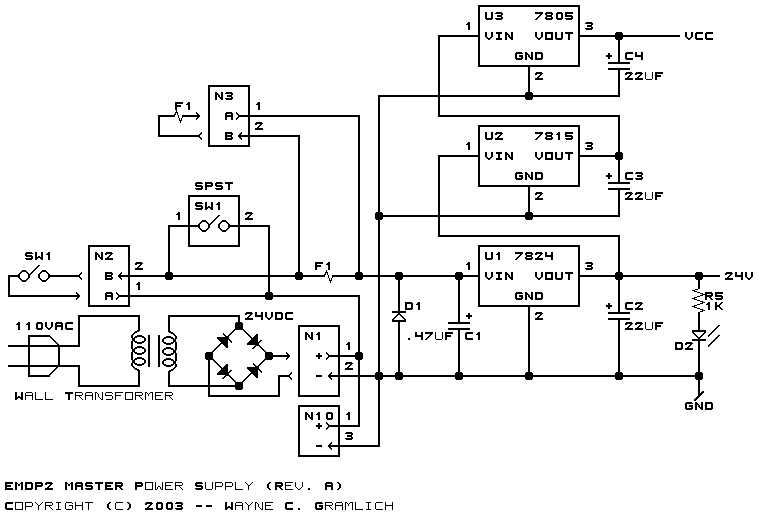
The schematic for the power supply is shown below:
The power supply takes its power from a 24-volt VDC wall wart either via N1, an on board connector, or via N10 an off-board connector. The power switch is either mounted on board or off-board via connector N2. The fuse can either be on board at F1 or off board via connector N3. Diode D1 is a shorting diode that should short the supply and burn out the fuse if the power supply gets hooked up backwards. The 24VDC is regulated to 24 volts via C1, U1, and C2. The 24Volts is regulated down to 15 volts via U2 and C3. The 15 volts is regulated down to 5 volts vis U3 and C4. N? is available if people wish to provide an source of power supply voltages and leave U1-U3 empty.
The schematic for the serial communication is shown below:
The schematic for the processor is shown below:
The schematic for the Digital to Analog converters is shown below:
The schematic for the RS-422 transceivers is shown below:
The following printed circuit board files are available:
Any fabrication issues will be listed here.