This is Revision B of the
Extensible Multiple Device Programmer
and it is currently a
work in progress.
EMDP1 -- Extensible Multiple Device Programmer 1 (Rev. B)
{Introduction goes here.}
The
parts list is kept in a separate file.
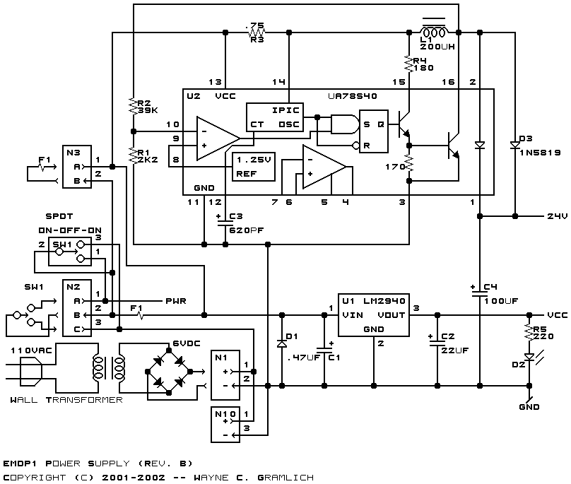
The schematic for the power supply is shown below:
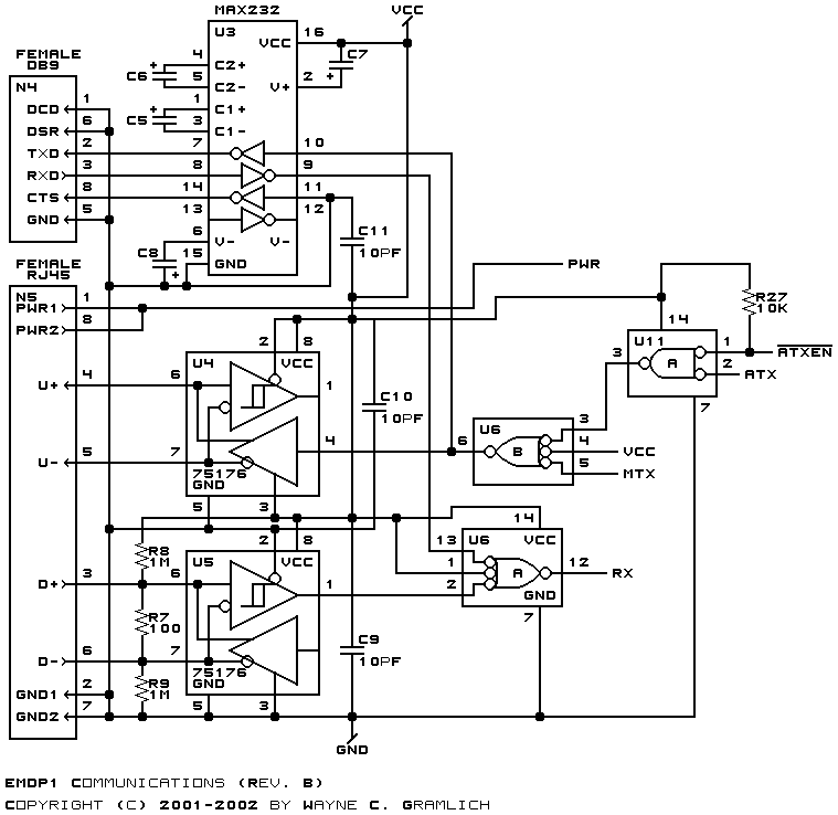
The schematic for the serial communication is
shown below:
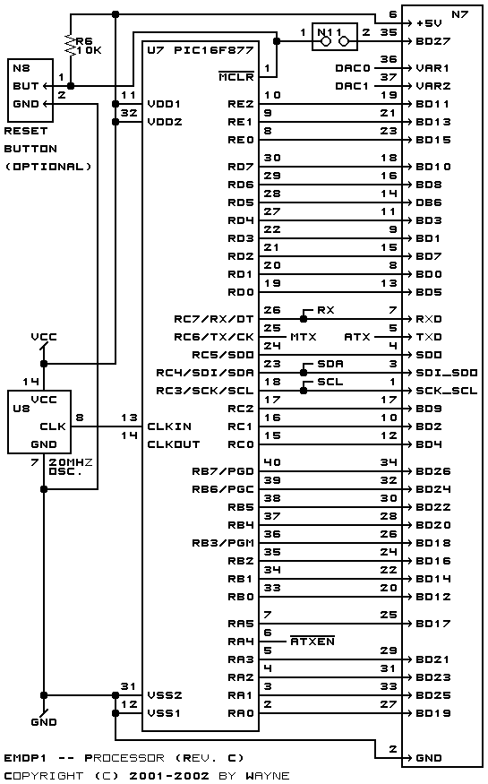
The schematic for the processor is
shown below:
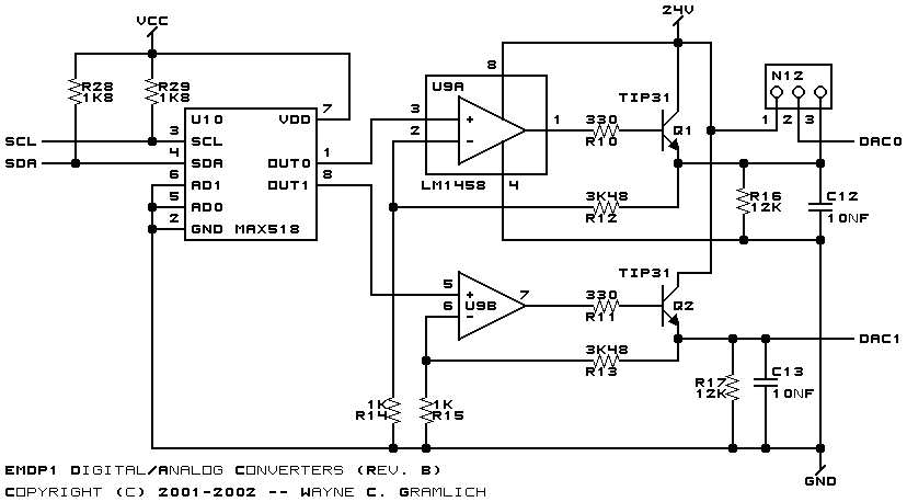
The schematic for the Digital to Analog converters
is shown below:
The following printed circuit board files
are available:
-
emdp1_artwork.png
-
The artwork (silk screen) layer.
-
emdp1_back.png
-
The back (solde)r side layer.
-
emdp1_front.png
-
The front (component) side layer.
-
emdp1.gal
-
The RS-274X (Gerber) artwork layer.
-
emdp1.gbl
-
The RS-274X (Gerber) back layer.
-
emdp1.gtl
-
The RS-274X (Gerber) front (top) layer.
-
emdp1.gml
-
The RS-274X (Gerber) mask layer.
-
emdp1.drl
-
The "Excellon" NC drill file
-
emdp1.tol
-
The drill tool rack file.
-
emdp1.ptl
-
The parts list (bill of materials.)
Any fabrication issues will be listed here.
Copyright (c) 2001-2002 by
Wayne C. Gramlich.
All rights reserved.