This is revision A of the EPROM GAL Plug28 and it is currently a work in progress.
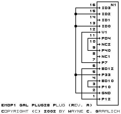
The EMDP1 GAL Plug28 plug is used to program the 26CV12 GAL.
The schematic for this revision is shown below:
The following printed circuit board files exist:
The table below shows were each of the BD signals winds up:
Pin EMDP1 Name Connected To 26CV12 Chip Pin 1 SCL U1-SCL 2 GND Ground GND 21 3 SDA U1-SDA 4 5 6 +5V Vcc 7 8 BD0 PROG_LED 9 BD1 ZIF40 Pin 39 VIL 27 10 BD2 ZIF40 Pin 27 SDOUT 15 11 BD3 ZIF40 Pin 29 VIL 17 12 BD4 ZIF40 Pin 30 VIL 18 13 BD5 ZIF40 Pin 14 STB- 14 14 BD6 ZIF40 Pin 31 VIL 19 15 BD7 ZIF40 Pin 13 SDIN 13 16 BD8 ZIF40 Pin 32 VIL 20 17 BD9 ZIF40 Pin 11 RA5 11 18 BD10 Plug Pin 4 RA4 10 19 BD11 ZIF40 Pin 9 RA3 9 20 BD12 Plug Pin 6 SCLK 12 21 BD13 ZIF40 Pin 8 VIL 8 22 BD14 ZIF40 Pin 6 RA2 6 23 BD15 ZIF40 Pin 5 RA1 5 24 BD16 ZIF40 Pin 36 VIL 24 25 BD17 ZIF40 Pin 4 RA0 4 26 BD18 ZIF40 Pin 38 VIL 26 27 BD19 ZIF40 Pin 37 VIL 25 28 BD20 ZIF40 Pin 3 P/V- 3 29 BD21 Plug Pin 13 (ID0) Ground 30 BD22 Plug Pin 14 (ID1) Float 31 BD23 Plug Pin 15 (ID2) Ground 32 BD24 Plug Pin 16 (ID3) Ground 33 BD25 Ground 34 BD26 Ground 35 BD27 36 VAR1 Plug Pin 12 (V1) VCC 7 37 VAR2 ZIF40 Pin 2 EDIT 2 38 39 40
The table below shows were each of the pins goes:
Pin 26CV12V8 BDx 1 VIL PD0 2 EDIT VAR2 3 P/V- BD20 4 RA0 BD17 5 RA1 BD15 6 RA2 BD14 7 VCC VAR1 8 VIL BD13 9 RA3 BD11 10 RA4 BD10 11 RA5 BD9 12 SCLK BD12 13 SDIN BD7 14 STB- BD5 15 SDOUT BD2 16 VIL PD1 17 VIL BD3 18 VIL BD4 19 VIL BD6 20 VIL BD8 21 GND GND 22 VIL PD2 23 VIL PD3 24 VIL BD16 25 VIL BD19 26 VIL BD18 27 VIL BD1 28 VIL PD4
Any fabrication issues will be listed here.