 |
This is what the Z axis looks like on its side and with
the hand wheel removed. By the way, my Z axis assembly
is quite old, since it is made out of bronze (the
yellowish/goldish metal.) All the newer assmblies are
made out of extruded steel. It is really amazing how
Sherline has been able to maintain compatability across
there product line over a period of three decades!
|

|
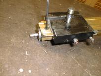
This is another view of the Z axis from the top showing
where the hand wheel used to be. (Yup, those are a couple
of my fingers.)
|
|
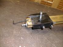
The thrust nut is removed by removing a small flat
head screw with an Allen wrench.
|
|
There is the rmoved flat head screw still attachted
to the end of the Allen wrench.
|

|
The thrust nut is supposed to slide off the lead screw shaft,
but my hand wheel had scored the shaft; thus, I could only
partially move the thrust nut. It is no big deal since
the entire lead screw is to be removed.
|
|
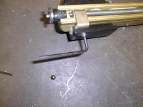
Remove the Allen head screw that attaches the saddle nut
to Z motor mount platform using an Allen wrench.
|

|
The removed Allen head screw has been removed, but it is
still attached to the Allen wrench.
|

|
The whole Z-axis lead screw is removed with the saddle nut
still attached. The white stuff in the Z axis column is
some old grease.
|

|
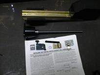
The backlash kit is shown on the white paper. It consists of
1) black level lock (left) with a black thumb screw sticking
out, 2) a longer Allen head screw, 3) a washer, 4) a black
lever bar with a pin sticking out of it, 5) a new bronze
saddle nut, and 6) a bronze locking lever.
|
|
In addition to the backlash kit, the CNC Z axis comes as a
preassembled unit with the CNC mount and lead screw sticking
out of it. This shown between the white paper and Z axis.
|

|
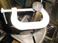
The round drill template is inserted into the top of the
Z-axis column and the holes are made as level as possible.
A C clamp is used to hold everything down. I found that
orienting the C clamp this way caused the Z axis to be
quite top heavy. In the next picture, the C clamp points
the other way.
|
|
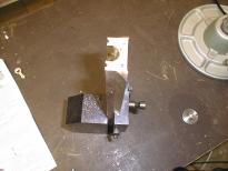
The two holes are drilled with a number 29 drill using
my drill press. Note that the C clamp is now reversed.
You can not see it in this picture, but my drill press
table is pretty far down the column. It would not be
possible to drill this hole using a table top drill
press.
|
|
Here is a picture of the Z axis column after the holes have
been drilled. The flash sort of washed out the holes in
this picture. Sorry.
|

|
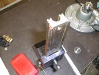
Now the holes are tapped with a #8-32 tap. As always when
tapping a hole, I back the tap up a quarter of turn every
half turn or so to break the chips. I am also certain to
stop when I hit the bottom so as not to break the tap.
|
|
Here is a picture of the tapped holes. No, really.
Ah, well, the flash really washed the holes out of this
picture. Sorry 'bout that.
|

|
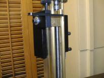
Next, I manully threaded the lock lever and the saddle nut
onto the Z-axis lead screw. The ball detent on the level
faces the saddle nut. I put the lock lever and saddle
nut close to the stepper motor adaptor in the hopes that
would get the lead screw aligned perfectly. It turned
out that the lead screw was pretty crooked. So I eventually
wound up putting the saddle nut down at the other end and
that wound up getting the lead screw vertially aligned.
|
|
The saddle nut is attached using the longer Allen
head nut that comes with the Z axis backlash kit.
Next, comes the washer, the black device with the
thumb screw, the motor mount platform, followed
by the saddle nut. Finally, I attach the black
plastic lever arm holder and tighten the black
thumb screw.
|
|
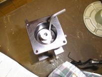
The Z axis lead screw assembly is attached to the
Z axis column using the two #8-32 Allen head screws.
As I sad before, I did not get alignment until I
ran the motor platform to the far end of the Z column.
|

|
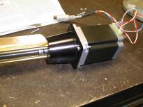
I tightned the set screw on the stepper motor flat
through the hole is the stepper motor mount. One
nice thing with having dual axis stepper motors is
that it is trivial to figure out where the flat is
inside CNC holder. (Actually, I forgot to take
this picture, so I wound up staging the picture
after everything was assembled.)
|
|
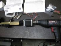
For each hole in the stepper motor mount, I use one
3/4 inch #6-32 round head machine screw with a serrated
lock washer and a hex nut. This rather blurry picture
shows the installation after one nut has been installed.
I installed the round head screw on the bottom and the
serrated lock washer and hex nut next to the stepper
motor. I figured there was less chance on anything
snagging on the exposed screw ends this way.
|
|
Greasing the lead screw is a good idea. To save time
I attache an electric drill to the shaft sticking out
the top of the stepper motor. Now, I can easily run
the saddle nut up and down the lead screw with ease.
|
|
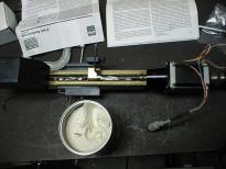
I just dab a little grease along the lead screw on
both sides of the saddle nut. Using the electric
drill, the saddle nut is run back and forth a few
times. to work the grease into the lead screw. That
big white thing at the bottom is a life time supply
of grease. For some reason, the hardware store does
not like to sell small tubes of grease anymore. I
used just a couple of small dabs.
|

|
The net result is pretty anti-climatic to look at.
There is a little grease collected at each end of
the lead screw and a small amount collected at the
entrance of the lock lever.
|
|
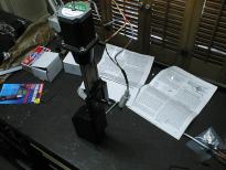
This rather dark picture shows the front of the
completed Z axis. I have propped it up on one
edge an Allen wrench to prevent it from tipping
over. It is rather top heavy at the moment.
|
|
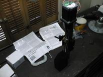
This dark picture shows the back side of the
completed Z asix assembly. (The work bench is
a little cluttered at the moment.)
|


