


This is the assembly of the CNC Buffer (Rev. A).
Below are the steps I used to assemble the rev. A CNC buffer board:
|
|
The bare board looks as follows: |
|
|
Next, I solder in the IC sockets. |
|
|
Then I added in the various 2×3, 2×5 and 2×13 .1" male headers. |
|
|
Next, I soldered in the capacitors and the 10K pull up resistor. Note that C12 has the + lead of the capacitor pointing down. All the other tantalum capacitors have the + lead pointing up. |
|
|
Finally, the 3 D connectors are soldered in. The total amount of time spent attaching the components to the board was 20 minutes. |
|
|
I found a box that was just barely big enough for the board. |
|
|
Most of my mounting holes did not work with this box since they were too close to the board edge. So I added a mounting on a empty section of real estate. |
|
|
I installed 3 spacers on the bottom of the board and placed it into the box. |
|
|
Using a sharp pointy object I scratched the outlines of the D connectors on the inside of the box. |
|
|
Using a sharp pointy object and a hammer like object, I marked to dimples for where the starter hole needed to be drilled. Afterwards, I flip the box over and invert the dimples using the pointing object and hammer like object. |
|
|
The next set of pictures are a little confusing. If first tried to drill the large pilot hole in one step. The drill wandered all over the place. |
|
|
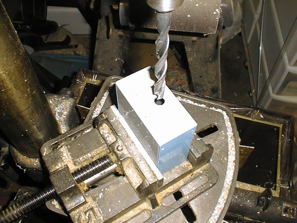
So, I changed to a smaller drill and drilled two pilot holes. Then I went back to the larger drill and made the holes bigger. The requirement here is to have a hole big enough for the nibbler tool. (By the way, I do not think I managed to get a picture of the nibbler tool in action.) |
|
|
The resulting holes for the nibber tool are shown. |
|
|
Using the nibbler tool, the initl slots are nibbled out. They are too small, so I use a whole bunch of metal files to file the larger. This takes a very long time (at least half an hour.) |
|
|
Eventually, I take the metal D connector covers off the PCB and I can press fit them into the holes. Note, that these are female connectors and the holes will eventuall have to be enlarged even more to be big enough for the male connctors. |
|
|
Using the press fit D connector covers, I first drill four small holes for the D connector screw mounts. |
|
|
You can see the small holes on either side. Unfortunately, the holes need to be unlarged so that the screw mounts can slide right through. |
|
|
So, an even larger hole is drilled where the pilot holes were drilled. |
|
|
You can see the much larger holes on each side of the D connector holes. |
|
|
Now there is even more filing to get a couple of male connectors to fit into the D connector holes. As usual, the filing takes a bunch of time -- say 15-20 minutes. |
|
|
Ad finally the the connectos fith though the holes. |
|
|
Now the board is place in and a little more filing is performed until the male conectors firmly attach to the female connectos on the board. Yeah. |
|
|
This is what it all looks like. If you look closely you can see there is a gap around both of the D connectors. |
|
|
There should be a few more pictures here, but I guess I just forgot. Using the PCB as a template, I drilled 3 holes on the bottom of the box to mount the PCB to. |
|
|
I drilled a power jack hole onto the other side of the box. |
|
|
It is .5" in diameter -- the largest twist drill I have. |
|
|
Finally, the power jack is mounted. It looks kind of stupid sticking out like that, but it is fully functional. |
|
|
Finally, board is screwed onto the bottom of the box with 3 #4-40 screws. It is not going any where. |
|
|
The power jack is soldered to a couple of wires and heat shrink tubing is attached. |